Continue to Site

Welcome to our site!

Electro Tech is an online community (with over 170,000 members) who enjoy talking about and building electronic circuits, projects and gadgets. To participate you need to register. Registration is free. Click here to register now.

  • Welcome to our site! Electro Tech is an online community (with over 170,000 members) who enjoy talking about and building electronic circuits, projects and gadgets. To participate you need to register. Registration is free. Click here to register now.

Temperature sensor

Status
Not open for further replies.

adrianvon

Member
Hi all,

I am using a PT1000 temperature sensor for a project. This sensor has 1000 ohms with zero °C. Now i want to connect this temperature sensor to a voltage comparator and therefore need a voltage output and not resistance. To do so i used a voltage divider.
Now my problem is that the output voltage is varying slightly (few milli volts from room temperature to 100°C). How can i increase the gap of the output voltage (for instance 10mV per 1°C) ??

Note that i can only use the PT1000 sensor.

Any help is appreciated.
Thanks is advance

hi adrian,
You could use a low value constant current source to drive the PT1000 and so develop a voltage across it.
Amplify the voltage using a OPA or if preferred use a LM393 comparator.
OK.

EDIT:
This is a previous example using the PT100,, a PT1000 would be similar
 

Attachments

  • AAesp02.gif
    AAesp02.gif
    30.7 KB · Views: 324
Last edited:
Hi ericgibbs. Thanks for your reply. Can you explain to me what is a 'low value constant current source' please ??

Is there a way to increase the output voltage gap using a voltage divider??

Thanks
 
Is there a way to increase the output voltage gap using a voltage divider??
Platinum sensors are accurate but have a very small change of resistance with temperature. There is no way to increase the voltage change due to this resistance change other than using a stable amplifier.

Other sensors, such as IC based sensors, or thermistors can generate a higher voltage change with temperature.
 
Hi ericgibbs. Thanks for your reply. Can you explain to me what is a 'low value constant current source' please ??

Is there a way to increase the output voltage gap using a voltage divider??

Thanks

hi,
The JFET is configured to supply a constant current of approx 100uA thru the PT1000.

The only way to increase the low level signal from the PT1000 is by using a operational amplifier.
The OPA will be also be configured to remove the offset voltage across the PT1000.

Do you follow.?
 
Hi all,

I found a circuit of an amplifier in the attached PDF file (page 14, Figure 4–13) were one can set the output as preferred (for instance if you know that the output voltage from the PT1000 will vary from 0.1V to 0.3V , you can set the output to give 1V when the input is 0.1V and 5V when the input is 0.3V).

Now my questions are:
1) Can i use an LM324 for this circuit??
2) Is it ok to use trim pots instead of resistors so that I can be able to set the exact calculated resistance value??
3) Can someone explain to me in a simple way how the circuit actually works??

All kind of help will be appreciated...
Thanks in advance.
 

Attachments

  • sloa076.pdf
    111.8 KB · Views: 387
The op amp used in the example circuit is from this family of op amps. The LM724 does not come close as a sub for many reasons. Among them is it is not a rail to rail op amp. There are many others also. You need a precision op amp and you need to consider things like temperature coefficients for all the parts used in designs like this for stability reasons. Yes, a trim pot could be used for Rg but again it would have fixed resistors on each side allowing a range of trim for the trim pot and again all resistors should be high quality resistors throughout the circuit. Overall the circuit is a pretty straight forward op amp circuit. Your prime consideration when working with circuits like this to do what you want to do is accuracy and precision. Thus the op amp and components need to be chosen carefully.

Just My Take
Ron
 
Thanks for your help Reloadron. I will check if the TLV247x family is available to buy locally otherwise i have to order online.
 
Hi Reloadron ,

Can i use a TLV2451 OP-AMP for the circuit mentioned in post #8 ??

The reason for using the TLV2451 instead of the TLV2472 (which is the op amp used in the example) is that i didn't find a shop which sell them.

Thanks in advance.
 
Yes, it should work.

Ron
 
Thanks for the reply.

Can i submerge the PT1000 probe (not with the wire) in water which will rise to 100°C ?? or do i have to buy a cover for it ?
 
Thanks for the reply.

Can i submerge the PT1000 probe (not with the wire) in water which will rise to 100°C ?? or do i have to buy a cover for it ?

You haven't mentioned the probe model? If the probe has a stainless steel or inconel sheath then yes. Other sheath materials would also work so it all depends on sheath material.

Ron
 
Ok thanks.

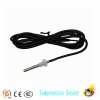
The probe is like the one in the picture below, which im assuming has a stainless steel probe.
 

Attachments

  • PT1000-Sensor-Dia-6mm-for-Solar-Hot-Water-Temperature-Sensation-sensor-solar-water-heater-parts.jpg
    PT1000-Sensor-Dia-6mm-for-Solar-Hot-Water-Temperature-Sensation-sensor-solar-water-heater-parts.jpg
    111.1 KB · Views: 1,113
Immersion at the temperatures you mention should be no problem at all.

Ron
 
Hi,

Finally the TLV2451 arrived. Now i have a problem since in the datasheet there is no pinouts labeling of the DIP package. Does someone know from where i can find it's pinouts ??

Below is the datasheet:

https://www.alldatasheet.com/datasheet-pdf/pdf/28971/TI/TLV2451.html

hi,
I see the pins outs for a TLV2451 on page #3 of that datasheet for the 8 pin surface mount, I would say the 8 pin DIL is the same..??

I will look around, let you know.

EDIT:
Its this one, the DIP is abbreviated to P
 

Attachments

  • AAesp02.gif
    AAesp02.gif
    3.1 KB · Views: 290
Last edited:
Status
Not open for further replies.

Latest threads

New Articles From Microcontroller Tips

Back
Top