Continue to Site

Welcome to our site!

Electro Tech is an online community (with over 170,000 members) who enjoy talking about and building electronic circuits, projects and gadgets. To participate you need to register. Registration is free. Click here to register now.

  • Welcome to our site! Electro Tech is an online community (with over 170,000 members) who enjoy talking about and building electronic circuits, projects and gadgets. To participate you need to register. Registration is free. Click here to register now.

Tell me about this signal

Status
Not open for further replies.

Crash Landing

New Member
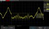
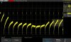
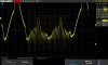
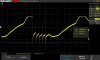
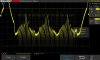
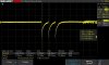
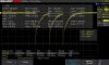
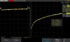
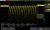
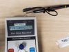
I have a device that is outputting the signal seen in the attached files. This signal comes from a two conductor 1/8" phono jack, and is normally sent to another device which controls a stepper motor. This signal is a number of pulses directly representing the number of steps for the motor to move. My goal is to bypass this device and produce this signal programmatically from a computer. Ideally there would be a small device external to the computer, connected to it via USB. The device would probably appear as a com port. It would have four to eight 2 conductor 1/8" phono jacks and I could simply send a number representing the port, and the number of pulses to the device from my program, and the pulses would be sent. I don't know what sort of signal this is. Is it AC current with the signal superimposed ? It all looks the same with the scope in AC or DC mode. I don't know if the 60 Hz background signal is because it is AC, or if it is hum leaking in. I read the pulses as being 1 millisecond apart. I have no idea how I could create such a signal unless I could do it as an audio signal. Theoretically I could record this signal as audio. I could record 100 versions, one for each possible number, and then selectively play them to produce the signal. But I don't have any idea if this is anything like an audio signal, or if audio would reproduce it. Perhaps there is an existing device that does what I need.
 

Attachments

  • SDS00013.jpg
    SDS00013.jpg
    98.6 KB · Views: 185
  • SDS00015.jpg
    SDS00015.jpg
    103.5 KB · Views: 192
  • SDS00019.jpg
    SDS00019.jpg
    100.1 KB · Views: 181
  • SDS00020.jpg
    SDS00020.jpg
    88 KB · Views: 191
  • SDS00026.jpg
    SDS00026.jpg
    119.5 KB · Views: 183
Stepper motors normally require two signals - step and direction. Your signal looks more complex than a simple step signal.

An arduino will appear as a com port and can easily do what you want if you can work out how to send step and direction signals.

I'm assuming that the steppers go in both directions.

Mike.
 
This is a simple carrier board I made for a project,
carrier.jpg

It consists of a Arduino Nano and two stepper motor boards. It can probably do what you need but driving the steppers directly.

Mike.
BTW, the stepper modules are much cheaper on ebay.
 
Hi,
Normally I control the direction of the motor at the Motion Controller. The signal I showed is sent to the motion controller from the time machine. The time machine is what I want to do without. The time machine cannot directly control direction. But in some literature I found, the motor direction is controlled by the signal being negative or positive. However, this motion controller may be modified for its purpose. I have been trying to determine if the 60 Hz signal is part of the signal. Or it may be
leakage.
The time machine has a battery and an external power port. It uses a transformer to get 12 VDC. I found the 60 Hzsignal is present even with the wall power disconnected, and even when the time machine is switched off. It is however, in a box containing three other boxes, and four transformers. So I don't know if it is part of the required signal, or if it is hum from induction.
 
Here is a link to information about the motor: **broken link removed**
Here is a link to some information about the time machine: **broken link removed**

You can see that the time machine is discontinued. I have two time machines, two motion controllers, and two motors, one for pan and one for tilt. It all works very well up to a point. I developed a complex program to plan a shoot. This program tells me all the settings for the two time machines. One problem is that I do long exposure time time lapse photography at night. A "Bulb" time is used to prevent the motors from moving during an exposure. When one time machine is used as a master to trigger the second as a slave, the slave isn't triggered until the bulb time is done. Now the second motor will move during the exposure because they are out of sync by the bulb time. I started using a Triggerbox to trigger the two time machines, and wrote an intervalometer program to trigger the triggerbox. The next problem is that, at best, out of 1000 frames, a time machine will fail to fire about 12 times minimum, when externally triggered. If I can replace the time machines I can do more elaborate things, more accurately.
I have of course, heard of Arduino. I don't know much more about it. I will definitely look at it. I am not sure it is a good idea to replace the motion controllers or not. It is simply that I have seen the simplicity of the signal coming from the time machine, and it is two conductor. From the motion controller to the motor, it is a DIN connector with several conductors.
 
Here is a link to the Sherline site. https://sherline.com/wp-content/uploads/2015/11/8800inst.pdf This is where I found This: "Slave Mode In this mode, the controller will wait for a low-going STEP command. As soon as it is found, the motor will move a single step in the forward direction if the DIRECTION input is high. If the DIRECTION input is low, the table will move a single step in the opposite direction." This Sherline motion controller looks exactly like mine. But it may be different and mine may have been modified for the purpose.
 
I think the 60 HZ signal is induced hum. I removed the time machine from the time lapse go kit. Now it was connected only to the oscilloscope. The signal was still there. I disconnected the plug from the time machine. Now there was only the oscilloscope probe and a wire connected to the scope. The signal was still there. Then I found if I moved the time machine close to the transformers the signal became about four times as strong. Moved as far away as I could still connected to the scope and, the signal was much weaker, but still there. It is not a clean electrical environment. I am sitting on a steel/concrete floor. there is overhead florescent lighting, and a closet a few feet away contains a large AC unit. I pulled the 120V plug on the go kit, depriving power from four transformers. the signal was still there, but now it was a clean sine wave. Now my current assumption is that the signal I want is a DC circuit with the power suddenly dropping to ground for each observed pulse. Can anyone confirm this ? Meanwhile i started reading about the Nano, and Arduino programming. I think I will have to study for a long time to figure out how to duplicate this signal. But it does look interesting.
 
Update...
1. Another possible cause or contributor is the fact that the setup I was measuring was all connected to a APC Smart UPS 600. I didn't even think of that before.
2. I have been hearing about Arduino, mostly from the ARRL Amateur Radio magazine. But I knew virtually nothing about Arduino. I read about the Nano, then about the language. Then I started looking at demo's, especially the code. It all looked very easy. I have programmed in C. So I bought a Nano, breadboards, LEDs, resistors, wires with pins. I successfully completed several simple projects, making LEDs blink and flash in several different ways. Then I got a Grove latching relay and got a simple intervalometer working. It can fire two cameras or two Time Machines, reliably. My simple test program fires for 200ms every 5 seconds. I am opening a closed circuit for 200 ms and that is the reliable way to fire the Time Machines. Now I have written a program that makes the relay behave like a Triggerbox, except NC rather than NO. It fires reliable using serial communication via the USB from my Intervalometer program I wrote for the Esper Triggerbox running on a windows computer, and sends a reply back to the program. This all solves one major problem I had. So I am about to make this into a permanent black box.
3. While I see the power of Arduino, I still don't know how to define the signal I am trying to duplicate. Is it an incredibly short closing of an open circuit ? If I could define this signal I could figure out if the Nano could produce it. This is what I was hoping someone on the forum could tell me.
4. I have been meaning to reproduce the oscilloscope images in a clean environment so there is no 60hz hum, to get a better and cleaner image to show. I hope to get to that today, or very soon.
5. I may now be addicted to Arduino. I have several unrelated projects already in the works.

So primarily, I need someone to tell me what sort of signal this is. Obviously it is some sort of pulses. They are 1ms apart. The code is simple. If I set the Time Machine to 44 steps per frame, the signal will have 44 pulses. Although I am not new to electronics, I have little experience with circuit level work. I have never seen a signal like this. How can it go straight down, and never up ? Is this an incredibly short square wave ? Perhaps I will understand if someone knows a catch word or phrase for this sort of pulse. Or perhaps someone could explain how this signal could be created mechanically.
 
Or perhaps someone could explain how to use paragraphs to make such a mass of text, readable.
 
I've been looking at the waveforms you show in post 1. The voltages look very low for any kind of reasonable motor control signals.

Can you please post either a schematic of the circuit and the points that you have the scope connected to marked? If you don't have a schematic, then a good resolution picture(s), again with the scope connection points marked, would help.
 
I don't know if the company who made the Time Machine will be willing to give out a schematic. The Time Machine has a 2 conductor mini-phono jack. For these tests I had a half cable, a two conductor cable with a 2 conductor plug, plugged into the jack. I had the leads connected to the two wires coming from the plug and jack. I plan to do the test again in a cleaner environment. This time I will connect directly to a bare plug so a cable will not contribute noise. I will take a picture to show you.
 
New Pictures ! This time I put the Time Machine and oscilloscope on a wooden table. There is almost no interference, no 60HZ signal as before. The time machine is running on a 9V. battery. This signal is of course a"3". I can never get the trigger to lock on these pulses, freezing the picture there. I checked this signal with a multimeter and could see nothing in any mode. In AC mode the signal looks more or less the same. the fourth picture is a "45". I have more pictures if it would help. note that this mystery signal does work. It talks to a Motion Controller that moves a rotary table. I'll follow up in a bit with a picture of the connections and setup.
 

Attachments

  • SDS00030.jpg
    SDS00030.jpg
    95.4 KB · Views: 181
  • SDS00037.jpg
    SDS00037.jpg
    118.7 KB · Views: 179
  • SDS00038.jpg
    SDS00038.jpg
    86.9 KB · Views: 182
  • SDS00005.jpg
    SDS00005.jpg
    126.5 KB · Views: 167
Here's a picture showing the probe connection to the Time Machine. The probe is connected to the leads from a plug that is plugged into the ramped pan jack which is normally connected to the Motion Controller. I hope this picture is not too large.
 

Attachments

  • 20191227_193938.jpg
    20191227_193938.jpg
    1.9 MB · Views: 173
Last edited:
Status
Not open for further replies.

Latest threads

New Articles From Microcontroller Tips

Back
Top