Hi,
I am building the TDA7000 FM radio using the schematics from this website TDA7000 FM Radio Receiver Circuit
**broken link removed**
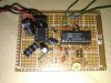
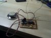
I added a LM386 amplifier to power a 8 ohm speaker. I use a trimmer capacitor 2-35pF.
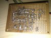
I build it on a perfboard and have tried to keep the connections as short as possible. All capacitors are ceramic. I have most of the capacitor values, except for C1 where I used 0.1uF, C10 - 160pF, and C12 - 56pF.
Upon first power on (and until now), all I can hear is white noise on the speaker. The white noise is stable with MUTE switch ON, e.g. artificially generated by the TDA7000 chip. With the MUTE switch OFF, the white noise remains but seems to vary slightly when I touch various parts of the board. However, I am unable to tune into any FM stations despite tuning the entire range of VC1 and trying various inductor sizes.
Any ideas how I can debug the circuit, other than keeping on checking connections and hope to find something wrongly connected? I have a 100Mhz oscilloscope, though I know it's probably useless at FM frequency. Any expected waveforms/voltages at various pins of the TDA7000?
Is there a way to know which FM frequency the circuit is trying to receive?
Also, regarding the antenna, what is the purpose of the seemingly complicated capacitor/resistor connections at pin 13, 14? The Philips datasheet simply suggests a capacitor to ground at pin 14, and another capacitor to the antenna at pin 13.
The photos of my circuit are attached. Any help is appreciated. Thanks.
I am building the TDA7000 FM radio using the schematics from this website TDA7000 FM Radio Receiver Circuit
**broken link removed**
I added a LM386 amplifier to power a 8 ohm speaker. I use a trimmer capacitor 2-35pF.
I build it on a perfboard and have tried to keep the connections as short as possible. All capacitors are ceramic. I have most of the capacitor values, except for C1 where I used 0.1uF, C10 - 160pF, and C12 - 56pF.
Upon first power on (and until now), all I can hear is white noise on the speaker. The white noise is stable with MUTE switch ON, e.g. artificially generated by the TDA7000 chip. With the MUTE switch OFF, the white noise remains but seems to vary slightly when I touch various parts of the board. However, I am unable to tune into any FM stations despite tuning the entire range of VC1 and trying various inductor sizes.
Any ideas how I can debug the circuit, other than keeping on checking connections and hope to find something wrongly connected? I have a 100Mhz oscilloscope, though I know it's probably useless at FM frequency. Any expected waveforms/voltages at various pins of the TDA7000?
Is there a way to know which FM frequency the circuit is trying to receive?
Also, regarding the antenna, what is the purpose of the seemingly complicated capacitor/resistor connections at pin 13, 14? The Philips datasheet simply suggests a capacitor to ground at pin 14, and another capacitor to the antenna at pin 13.
The photos of my circuit are attached. Any help is appreciated. Thanks.
")
