boolagoosh
New Member
I am attempting to create a device to light a row of leds about 20 wide as follows
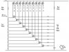
leds---- 0 0 0 0 0 0 0 0 0 0 0 0 0 0 0 0 0 0 0 0
circut---0 1 2 3 4 5 6 7 8 9 9 8 7 6 5 4 3 2 1 0
When supplied with a constant 12 volts, I want the 9s to light up first, joined next by the 8s, then the 7s etc........
it will start small and grow out as more leds turn on.
its for a third brake light in my car :?:
")
