Continue to Site

Welcome to our site!

Electro Tech is an online community (with over 170,000 members) who enjoy talking about and building electronic circuits, projects and gadgets. To participate you need to register. Registration is free. Click here to register now.

  • Welcome to our site! Electro Tech is an online community (with over 170,000 members) who enjoy talking about and building electronic circuits, projects and gadgets. To participate you need to register. Registration is free. Click here to register now.

Switching Regulator Overcurrent Protection

Status
Not open for further replies.

jnnewton

Member
So I have two designs for a 12(ish) to 5V buck converter. The first one utilizes an older LM2675. The second is a newer TPS563200. I'm testing the new one, and everything is fine except the overcurrent protection does not work. If I short the output of the old one and then remove the short, 5V rail comes back on. If I short the output of the new one, I destroy the IC. Now, the old one simply said "Thermal Shutdown and Current Limit Protection", while the new one says "Cycle By Cycle Overcurrent Limit". Have I made a poor upgrade choice, or a poor implementation?

Some more test specs: input 12V, output 5V, pre-short Load: 400mA.

Datasheets:
https://www.ti.com/lit/ds/symlink/lm2675.pdf
https://www.ti.com/lit/ds/symlink/tps563200.pdf

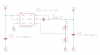
New Schematic Attached.
 

Attachments

  • TPS563200.png
    TPS563200.png
    18.4 KB · Views: 197
Is it possible the current rating for the inductor is not high enough?
 
I don,t know why you are having problems. Saturating the core is a possible reason. (what RonV said)
Also I noticed the coil inductance should be 3.3 to 4.7uH. You could try the larger coil. That would give the IC slightly longer to respond to a short.
Could be a bad layout of the PCB.
I would think the new IC would respond faster to a short.
 
Inductor Used:
CLF6045T-3R3N
**broken link removed**
Current ratings are > 3A (and therefore > IC rating) which should be good.

ronsimpson: the recommended range for 5V output is actually 2.2 to 4.7, with 3.3 being the typical. Why would the mfg recommend a coil inductance that could be the cause of one of their features not working?

That being said, I have a couple of 4.7uH ones with lower current ratings I could try, but i'm guessing that's not going to work. I'll order a 4.7uH with sufficient current rating and try that.

The layout is almost a copy paste of TI's layout, with slight variations in package shape / size (most noteably larger fb resistors)
 
Last edited:
I am looking at the data sheet. Location 9.2.2.1
They say the RMS current is 3.014A and the peak is 3.503A. (running not a short)
They chose a inductor rated for PK=7.3A and RMS=4.9A
Your inductor at 3.1A drops 10% in inductance. The inductance will drop fast above that. see page 8 of data.

I could not get a good idea as to what happens at short circuit but:
The data sheet said: output current limit (3.5/4.2/5.3A) (if this is RMS current they the PK current is higher)
Your inductor is 1uH at 5.3A. This caused the current to peak up very fast.

I would try a higher current coil.
You can parallel or series two. (parallel two 4.7 or 6.8) or (series two 2.2 or 1.5)
 
I have direct experience with several National Semiconductor devices including the 2675, and a couple of TI non-NS parts (but not yours specifically). In my experience, the NS parts just plain work better. They are easier to work with, not as finicky, more tolerant of external components and conditions - I know, all subjective terms, no data, yaddi yaddi. Still, The only regulator chips that have given me more grief than TI are from Maxim. So to your question about making a poor choice - can't say without a schematic, BOM, and layout. But my gut says definitely maybe.

ak
 
Last edited:
ronsimpson:
Supposedly if i follow equations 8,9,10 I should arrive at an approved value. Now, the big unknown in that is the Io ("output current"). In a dead short this is whatever the IC can provide without popping (I would guess this to be 5.3A) as the max output current limit? I tried to use some estimated actual application values for these initially, not thinking that the protection feature was dependent. Let's re-run with 5.3A as the Io

Ilp-p = Vout / Vin(max) * (Vin(max) - Vout) / Lo*fsw = 5/14 * (14-5)/(3.3e-6 * 650e3) = 1.50A
Ilpeak = Io+Ilp-p/2 = 5.3+1.5/2 = 6.8A
Ilo(rms) = sqrt(5.3^2+1.5^2/12) = 5.32A

This seems to be closer to the inductor you mentioned above. The probably simply went off of the 6.8A for the peak for this situation, but i would think they'd want to cover the rms as well.

As for my inductor being 1uH @ 5.3A, yeah, I didn't consider the inductor at the shorted current, I ran everything for 3A, and probably not correctly, then checked with ti's webench, which probably doesn't check for this sort of thing.

That all sounds fine and good, but it seems like we're sizing the inductor to run at the shorted current, when what we really want to do is have enough inductance to allow enough time for the IC to do the current limit right?

So for a single "ON" cycle, with the RMS current in the inductor already @ 3A, what happens in the 1/650kHz = 1.538uS when the output goes short? How fast does the current rise, in the time where the chip hasn't done anything yet. It seems like it can rise about up to about 5A in one cycle (crude ltspice attempt), so that would put our peak current around 8A.

And as the inductance drops, that rise happens faster, so really, I want the 3.3u Inductor, with an 8A+ peak current and an rms > greater than whatever my operating point is, or up to 4.7u, and i can get down in the 6-7A peak range.

Thanks for the discussion. I've got some stuff to try.
 
Ilp-p = Vout / Vin(max) * (Vin(max) - Vout) / Lo*fsw = 5/14 * (14-5)/(3.3e-6 * 650e3) = 1.50A
Put 1uH into the equation and the peak heads up very fast.

I agree, we got the problem identified. Probably with a 8A coil things will be different.
 
So I received replacement switchers and inductors today.

I have the following inductors:

CLF10040T-3R3N - 3.3uH, rolls off above 6A, 6.6A rating based on inductance change rate
CLF12555T-3R3N - 3.3uH, rolls off above 10A, 11.4A rating based on inductance change rate

CLF12555T-3R3N: passed 3-4 short tests, switch to CLF10040: failed short test.

I wonder how much margin I have between this thing frying or not. Is our 8A coil estimate a good one? I doubt its viability due to it being based in ltspice, a program I can barely call myself a beginner at using it.
LTSpice doesn't model saturation, but you can estimate it by plugging in the following for the inductor value:
Flux= 33u*3*tanh(X*.08) Where 33u is your inductor value and 3 is it's saturation current in amps.
It still won't tell you you blew up your chip but you can get an idea how high the current goes.:woot:
 
I wonder how much margin I have between this thing frying or not. Is our 8A coil estimate a good one? I doubt its viability due to it being based in ltspice, a program I can barely call myself a beginner at using it.
I think 8A is close based on:
1) math
2) The idea that 6A failed and 11A passed.
3) Here, I would put a current probe on the coil or IC, using an o-scope.
 
Status
Not open for further replies.

Latest threads

Back
Top