Continue to Site

Welcome to our site!

Electro Tech is an online community (with over 170,000 members) who enjoy talking about and building electronic circuits, projects and gadgets. To participate you need to register. Registration is free. Click here to register now.

  • Welcome to our site! Electro Tech is an online community (with over 170,000 members) who enjoy talking about and building electronic circuits, projects and gadgets. To participate you need to register. Registration is free. Click here to register now.

Surplus Displays

Status
Not open for further replies.

HarveyH42

Banned
A few weeks ago, I picked up a couple of these mixed part boxes from Electronic Goldmine: Ginormous Surprise Box-The Electronic Goldmine

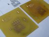
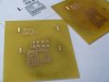
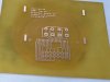
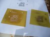
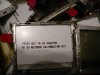
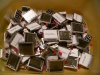
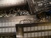
Just got started sorting out the goodies, and found I had a considerable quantity of these little cell phone LCDs, not much use, since they have the rubber 'zebra-strip' connector. Was online, getting data sheets for some of the other parts, and looked into these as well. Nothing from the manufacturer, but another major find: Outguessing the machine Goldmine Electronics LCD pinout (mini-teardown)

Website gives a PCB layout for a breakout board, some sample code (unfortunately, PIC), and a lot of info on the display. Really nice work, and I have 51 of these thing. At 2 for $1.00 if you order them, still a great deal on 128 x 65 LCD, and figured I share. I have a week off coming up, will try hooking one up then. Hope Pulsar paper will handle the fine lines, would hate to have to resort to 'Magazine paper' :)...

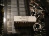
Also got about 20 yellow dual digit 7-segment displays (leads bent to hell), got the data sheet, CA, and pins for each segment, so easy hook up.

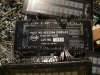
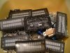
Got 8 vacuum glass displays, also with bent leads... that look interesting. Found nothing online yet, but just started looking. They are 2 lines x 10 character. Kind of thin, so hoping lower voltage, maybe automotive. Could use some help on these. Haven't hooked power yet, kind of hoping they are blue.

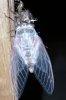
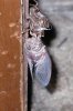
The bug, is a cicada, that used my door frame to emerge on. Looked pretty cool, had to move it outside, so I could close the door.
 

Attachments

  • P1010447.JPG
    P1010447.JPG
    344.8 KB · Views: 273
  • P1010448.JPG
    P1010448.JPG
    502.2 KB · Views: 275
  • P1010451.JPG
    P1010451.JPG
    317.2 KB · Views: 243
  • P1010453.JPG
    P1010453.JPG
    380 KB · Views: 241
  • P1010456.JPG
    P1010456.JPG
    611.2 KB · Views: 280
  • P1010457.JPG
    P1010457.JPG
    524.1 KB · Views: 259
  • P1010459.JPG
    P1010459.JPG
    633.5 KB · Views: 238
  • P1010436.JPG
    P1010436.JPG
    397.6 KB · Views: 249
  • P1010444.JPG
    P1010444.JPG
    424.1 KB · Views: 274
Just think of the amount of discarded components due to upgrading, updating and obsolescence.
It started 25 years ago when Black and White TV changed to colour.
The out-dated components could fill a line-up of trucks.

I can see a $1,000 worth of displays on the bench - you must be able to something interesting with them.
 
I've been thinking about using one for a small portable projection type device. Have to get one hooked up, and see what's involved in using the LCDs. Might need a bigger microcontroller. I think 4k is the largest, and not sure how much space I'll need for images or character tables. Should be enough to play some though. Don't often stumble across house numbered parts, that somebody has figured out.
 
For a second I thought that the bug was in the box, then I thought that it could have some infectious Asian bug disease! All in all would you say its worth ordering that box?
 
For a second I thought that the bug was in the box, then I thought that it could have some infectious Asian bug disease! All in all would you say its worth ordering that box?

Definitely worth the $12.95, got quite a few other nice items as well as the displays. Not much in the component department this time, but happy with what I got. Several wireless alarm items (pir, window break sensor, keypads) all seem to be intact, and unopened boxes. Pair of stepper motors, some wallwarts, submersible pump, close-loop transmitter, telephone loud ringer.
The parts were mostly displays, glass diodes, small transistors, bunch of tiny surface mount chips, and about a pound of mixed small screws (nice).

Considering the catalog prices, this was a very good value, even if I don't find a use for 2/3 of the items. The close-loop transmitter something I've been considering for a robot lawnmower project. Need to find a good motor, or cheap rechargeable lawnmower. Anyway, surprise boxes aren't for everyone, I only get the occasionally. Usually get some useful items, get a few unusual items to figure out, sometimes it just fun to figure out what to do with items.

Oh, the cicada wasn't in the box, they are all over down here. Harmless, I guess. You hear them, but seldom see them alive, and this is the first one I've seen emerge from it's beetle skin.
 
Totally depressing... I've got a PDF of the PCB art, but couldn't figure out how to mirror for printing. Messed around trying to figure out how to make my own with Eagle, mostly just messed it up... Will keep at Eagle, but was hoping to just print out the board, and play. Wasn't expecting so much frustration, just to get started.

Upload all the files, so they don't get lost. Data sheet might be useful in the future.
 

Attachments

  • LCD Board.pdf
    13.9 KB · Views: 309
  • s6b0755.pdf
    586.2 KB · Views: 295
  • goldlcd.zip
    55.5 KB · Views: 161
1. open the PDF and make the PCB art large on the screen
2. press printscrn (puts screen image in clipboard)
3. open any photo edit program like photshop etc
4. edit->paste->to new image
5. crop the image down so it's just the PCB
6. edit->flip->horiz flip image (mirror)
6. save as a .GIF or .BMP

Now you have the PCB art as a image, that is reversed. It only takes a few seconds.

You may be able to print it from the photo edit program (may need resizing), but I find it easier to import the image into a word document where I can resize it in mm to exact physical size and print it from there.
 
Wow, very cool pile o' stuff there... may have to get one of those boxes and hope I get something cool like that too :D

You might have good luck with Irfanview as a quick, simple photo editor. Good luck, very curious to see what you build.
 
1. open the PDF and make the PCB art large on the screen
2. press printscrn (puts screen image in clipboard)
3. open any photo edit program like photshop etc
4. edit->paste->to new image
5. crop the image down so it's just the PCB
6. edit->flip->horiz flip image (mirror)
6. save as a .GIF or .BMP

Now you have the PCB art as a image, that is reversed. It only takes a few seconds.

You may be able to print it from the photo edit program (may need resizing), but I find it easier to import the image into a word document where I can resize it in mm to exact physical size and print it from there.

Tried something similar, but got lousy results. The spacing on the 'Zebra-strip' need to be fairly precise. I selected the image in Acrobat, and copied it to the clip board. Pasted it into Corel Photopaint, found it to be kind of low res, and messy. Cleaned it up, but it printed slightly larger than the original. Wasn't confident enough to play with it more. The rubber strip connector has very fine lines, not much tolerance. Figure I'll have to learn Eagle, since there is a part for the library in the zip file. The PDF board only has 4 capacitors, the one in Eagle has 10...
 
Pasted it into Corel Photopaint, found it to be kind of low res, and messy.
If you zoom in, while in Adobe, and fill the entire screen with the image before copying to the clip-board using the snapshot tool, it'll look much better.
 
Tried the zoom/capture

Tried the zoom, and got a better capture, but still jagged. Decided to give it a shot, so etched a couple. Haven't drilled it yet, need to figure a slick way to do the slots. Hope I got the scale close enough. Have a few spots I need to patch on the boards, the jagged lines allowed the etch to nearly cut a few traces. First time running .032 board through the laminator, and it didn't seem any different from the .016 board I been using. Also used the paper cutter on it, worked fine as well.

While waiting for the images to upload, decided to do some drilling. Got lucky, one of my thicker bits was a router, sliced right through. Got a little wild on the first slot, wasn't prepared for it to cut so easy. Did okay with the rest of them. LCD snapped right in, so figure I must be pretty close. Will go dig up some caps and double row headers. Will have to build a cable as well. Pretty sure I've got some 14 wire ribbon and an IDC for it, have to figure something to plug into a PCB, IC socket maybe.
 

Attachments

  • P1010471.JPG
    P1010471.JPG
    197 KB · Views: 223
  • P1010474.JPG
    P1010474.JPG
    189.6 KB · Views: 186
  • P1010479.JPG
    P1010479.JPG
    167.8 KB · Views: 223
  • P1010482.JPG
    P1010482.JPG
    185.4 KB · Views: 188
Hey HarveyH, did you ever get this display going? I have a TON of these from the goldmine and would like to know how your making on with them?
 
I've got the board assembled, but still haven't built a cable for it yet. I've got 14-wire ribbon cable, some 14 pin IDC connectors, but haven't decided on how I'm going to make it come out on a breadboard yet. Want a single line, but think an IC socket might have to do. Got some long lead, wire-wrap style some place, haven't figured out where the ended up, been about 10 years since I last saw them.

Still trying to decipher the data sheet, PIC code. I'm using AVR, so have to figure out my own intialization and stuff. I used the artwork from the PDF, which only had 4 capacitors. The Eagle version has 5 more, attached to V0-V4 pins, haven't figured if they are needed yet.

Wish I could find some AVR code for these, way too much stuff to digest.
 
Thats exactly why I haven't even got the board done yet. I'm also using AVR, and don't have much experience with them, even driving documented normal text LCD's aren't completely easy for me. Hopefully the code part won't be too bad, I must have over 50 of these LCD screens sitting in a box, if I can make them useful with a pcb, I could have a batch done at a board house (maybe make a version with pins to stick directly into a breadboard or something).

Keep us posted, I'm sure others will be interested in some progress as well. If I can help out at all, please let me know, or I'm sure some around here can help out too.

Thanks for doing some dev work on this, should be an interesting project!
 
Status
Not open for further replies.

Latest threads

New Articles From Microcontroller Tips

Back
Top