Fieldhouse
New Member
Hi Guys!
I live in a rural house without hookup to mains electric which in itself brings up its own problems but not least the fact that I have to generate my own electricity using solar panels and a generator! Hence the problem with this circuit board.. I'm afraid it got a belt of high voltage from the generator and refuses to play!
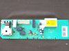
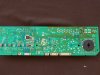
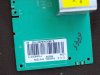
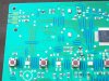
It's the electronic control module from a Bluesky 1030bf washing machine. This controls the programming/cycles on the machine. Please see pictures for the damage..
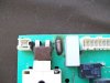
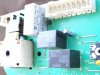
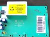
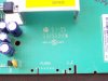
I've checked for burn marks, solder joint damage etc. and as far as I can see there are 2 affected components.. the resistor (burnt) marked R1 on pcb and there was a capacitor next to it (now removed, was the same as the other capacitors on the board VE09 0301 7Ku) marked VDR1 on pcb which had kind of exploded!
I can't identify the markings on the resistor due to it's burn out. I can just make out that it had 4 maybe 5 colour bands. One at one end is definitely brown, then one at the other is 90% black and there is one in the middle, looks pink now but may have been lilac?
The fault that all this causes is that when I plug the module in it just sends all the lights on and freezes.
I have contacted the manufacturers of the module (EGO systems in Germany) but they haven't replied. I managed to contact EGO in the UK but they said they didn't have access to this information but would try..
I found this but it's not very specific..
**broken link removed**
..it's the Type 6800 on that webpage.
Apart from that I just can't get any other info on this module.
My question is, then, would it be possible, for some of you out there, more experienced than myself (!) to take an educated guess about what this resistor would be trying to achieve and hence what it's value might be?
I can supply any other info off the other components on the board etc. if any of you have any ideas and need that kind of extra info..
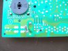
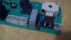
Since some of the pictures were taken earlier and since then I have been to an electronics components shop and they gave me a new capacitor that they said was the same, so I have fitted that and tested the washer again but it still won't start. See the last pic which shows the capacitor (blue, with CNR 14D431K) now fitted.
I have taken the resistor out for a closer look in the past hence the rather shoddy soldering I'm afraid!
Thanks in advance for any help you can give.
I live in a rural house without hookup to mains electric which in itself brings up its own problems but not least the fact that I have to generate my own electricity using solar panels and a generator! Hence the problem with this circuit board.. I'm afraid it got a belt of high voltage from the generator and refuses to play!
It's the electronic control module from a Bluesky 1030bf washing machine. This controls the programming/cycles on the machine. Please see pictures for the damage..
I've checked for burn marks, solder joint damage etc. and as far as I can see there are 2 affected components.. the resistor (burnt) marked R1 on pcb and there was a capacitor next to it (now removed, was the same as the other capacitors on the board VE09 0301 7Ku) marked VDR1 on pcb which had kind of exploded!
I can't identify the markings on the resistor due to it's burn out. I can just make out that it had 4 maybe 5 colour bands. One at one end is definitely brown, then one at the other is 90% black and there is one in the middle, looks pink now but may have been lilac?
The fault that all this causes is that when I plug the module in it just sends all the lights on and freezes.
I have contacted the manufacturers of the module (EGO systems in Germany) but they haven't replied. I managed to contact EGO in the UK but they said they didn't have access to this information but would try..
I found this but it's not very specific..
**broken link removed**
..it's the Type 6800 on that webpage.
Apart from that I just can't get any other info on this module.
My question is, then, would it be possible, for some of you out there, more experienced than myself (!) to take an educated guess about what this resistor would be trying to achieve and hence what it's value might be?
I can supply any other info off the other components on the board etc. if any of you have any ideas and need that kind of extra info..
Since some of the pictures were taken earlier and since then I have been to an electronics components shop and they gave me a new capacitor that they said was the same, so I have fitted that and tested the washer again but it still won't start. See the last pic which shows the capacitor (blue, with CNR 14D431K) now fitted.
I have taken the resistor out for a closer look in the past hence the rather shoddy soldering I'm afraid!
Thanks in advance for any help you can give.
Attachments
-
 102_0410.JPG54.6 KB · Views: 738
 -
 102_0413.JPG56.7 KB · Views: 706
 -
 102_0415.JPG64.5 KB · Views: 661
 -
 102_0417.JPG71.3 KB · Views: 635
 -
 102_0411.JPG47.2 KB · Views: 661
 -
 102_0408.JPG62.2 KB · Views: 627
 -
 102_0409.JPG57.2 KB · Views: 637
 -
 102_0412.JPG51.2 KB · Views: 634
 -
 102_0414.JPG75.3 KB · Views: 696
 -
 102_3297.JPG190.6 KB · Views: 698
