Continue to Site

Welcome to our site!

Electro Tech is an online community (with over 170,000 members) who enjoy talking about and building electronic circuits, projects and gadgets. To participate you need to register. Registration is free. Click here to register now.

  • Welcome to our site! Electro Tech is an online community (with over 170,000 members) who enjoy talking about and building electronic circuits, projects and gadgets. To participate you need to register. Registration is free. Click here to register now.

Surface mount heat sinks

Status
Not open for further replies.
What I did, Was when laying out my pcp. I added two through holes for a heatsink that would cover my LM317 regulators. after assembling the brd I mounted the heatsink over the tops of them w/ thermal paste and used 0-80 screws through the brd to retain them. I then added a cooling fan, both the fan and heat sink were scavanged from a computer mother brd. I also allowed for the recommended thermal pad requirements from the data sheet just to be safe. Hope that helps how I did it.
 
Hi

Thanks for the link.

I am trying to understand its contents.

I am using
moset IRLR3714Z
Diode 8EWF10S

and will be driving 8 amps, 12v load.
 
Hello

I am building a DC PWM board.

I am designing my own board on diptrace that I intend to etch myself. and would like to use surface mount components.

I need to use an 8 ampsurface mount diode ( https://www.electro-tech-online.com/custompdfs/2013/02/0900766b80af50a6.pdf)


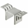
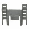
I understand that i will need to use a heatsink but i do not now how to do this with surface mount devices.

Can any one explain how this is done?

Thanks.
Charlie


Hi,

How did you determine that you need this somewhat special kind of diode?

The heatsink would normally be 1 square inch of clad on a FR-4 or similar board.

Note that the rating is not a straight 8 amps, it's only 8 amps at 50 percent duty cycle.
 
hi

I chose it as it was fast recovery, cheap and in surface mount. The application not says it uses are; Output rectification and freewheeling diode in inverters,
choppers and converters. The use for this one is as a free wheeling diode.


I did not notice the 8 amps at 50% duty cycle. Please could you show me one that is more suitable for use?

It needs to be at least 8 amp and surface mountable and suitable for 0 - 100% duty cycle.

You say the surface mount is normally 1 square inch of fr4. I think you may be wrong as the heat dissipated by this amount of
power will be too much for the 1 inch.

Most I have seen have a heat sink on them.
 
AE10774TR
I have this type. It needs to connect to copper and the copper connect to the hot part.
7109DG
I like this one.
 

Attachments

  • V-1100-SMD%5EB.JPG
    V-1100-SMD%5EB.JPG
    97.9 KB · Views: 193
  • 7109DG.JPG
    7109DG.JPG
    76.6 KB · Views: 174
For the forward voltage drop at 8 amps from the spec you will generate over 9 watts of heat (assuming your requirement is 100% duty cycle). That is a very large heatsink. You would be better off finding a diode with less voltage drop at 8 amps, assuming it meets your switching speed.
 
8EWF10S
That is a 1000 volt diode. It will have a very bad Vf. 1.3V
MBR1045
This diode is 45 V at 10A with a Vf that is much smaller. 0.47V
 

Attachments

  • 8EWF..S,%201000%20to%201200V.pdf
    156.9 KB · Views: 176
  • mbrfb1035.pdf
    130.1 KB · Views: 202
Hi

Yes it is driving a motor.

Unfortunatly I will not now the motor charactorisitcs as it will be used on different motors from different manufacturers.

All I can now is that they will all be 12V and 8 amps.

Thanks for your help everyone.
 
Can someone explain to me what i need to consider with regards to switching speed and duty cycle?

Usually schottky diodes are used for low voltage applications like yours. In addition to having low voltage drop they are very fast so switching speed is not an issue. Sometimes if the FET you are using in your PWM is very fast you may need to worry a little about reverse recovery time. Again it is usually not a concern with schottky diodes.
The reason I ask about the motor was for duty cycle power rating on your diode. Since it is unknown we must assume that the spec is 8 amps maximum. This would mean that the motor resistance is 1.5 ohms and it would draw 8 amps at 12 volts if it weren't allowed to turn and maximum voltage was applied. If this is the case the average diode current will be 1/2 of the motor current. This is because for 50% of the time the current is thru the FET and then the other 50% thru the diode.
 
AE10774TR
I have this type. It needs to connect to copper and the copper connect to the hot part.
7109DG
I like this one.

I've used similar heatsinks, and they are very good at removing heat from SMT devices.

So good, in fact, that they are almost impossible to solder with your soldering iron......it will suck all the heat out.
You'll have to use a hot-air gun to preheat the heatsink and surrounding pad area before soldering it.
 
They are self excited pumps.

So can I use reflow to solder the heatsinks?

Do I need some sort of compund between the diode junction and the copper board or can I use solder paste?
 
All I can now is that they will all be 12V and 8 amps.
Is that running current or the much higher stall current?
 
Status
Not open for further replies.

Latest threads

Back
Top