Continue to Site

Welcome to our site!

Electro Tech is an online community (with over 170,000 members) who enjoy talking about and building electronic circuits, projects and gadgets. To participate you need to register. Registration is free. Click here to register now.

  • Welcome to our site! Electro Tech is an online community (with over 170,000 members) who enjoy talking about and building electronic circuits, projects and gadgets. To participate you need to register. Registration is free. Click here to register now.

Supplying reactive power.

Status
Not open for further replies.

alphacat

New Member
I read that when a motor needs reactive power, it is not necessary to go all the way back to electric power generators on the transmission grid to get it, because you can simply put a capacitor at the location of the motor and it will provide the VARs needed by the motor.
If we treat the motor as an inductor, then without the capacitor we receive a RL circuit:
motor-jpg.29624


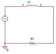
How is it suggested to connect the capacitor?
If you connect the capacitor in parallel to the RL, then you'd increase the current drawn from the power line, since (R+XL) < (R+XL)||XC, and would therefore increase the reactive power supplied by the power grid, so I dont see how it helped.
 

Attachments

  • motor.JPG
    motor.JPG
    3.9 KB · Views: 373
Motor run capacitors are usually in series as far as I know.
 
Motor run capacitors are usually in series as far as I know.
The motor run capacitor is not for power factor correction, it's to provide phase-shift for a second winding to give a rotating magnetic field for a single-phase motor.

The capacitor does add reactive current, but it has a leading phase angle whereas a motor's (inductor) reactive current has a lagging phase angle. A power factor correction capacitor would be in parallel with the motor. The leading phase reactive current it draws, which if it's the proper size, will cancel the lagging phase current from the motor.

The power companies often add capacitors across the AC lines near industrial areas for the purpose of canceling the lag reactive magnetizing current from motors and transformers.
 
Thanks for the correction cruts I think I understand what you said. Question though, how do you value the capacitance you use to provide the buffering? A capacitor in parallel with a motor is going to waste at least some nominal current from it's AC impedance, I've always had a bad practical understanding of lead/lag effect of impedance with motors and capacitors though, confuses me all the time.
 
Last edited:
True. It will waste a small amount of power but the VA load correction it makes saves far more power just by dropping the unavoidable line losses of the supply wires.

I have 100 uf 370 volt power factor correction capacitors, I regularly use for building phase converters, that are roughly the size and volume of a 12 ounce pop can.
At 240 VAC they carry around 8 amps. So 240 x 8 = 1920 VA Even after hours of running at that level they do not warm up enough for me to feel a difference. So its maybe a few watts internal losses at most.

However if you calculate the line loss savings of say going from a 30 amp load to a 22 amp load on 300 feet of 10 ga copper wire you can see a measurable efficiency gain just from dropping the wire loss amounts.
 
Thanks for the correction cruts I think I understand what you said. Question though, how do you value the capacitance you use to provide the buffering? A capacitor in parallel with a motor is going to waste at least some nominal current from it's AC impedance,
You just set the capacitive reactance 1/(2pi x f x c) equal to the motor inductive reactance. Or if you know the motor reactive current you just select a capacitor with the same reactive current at the supply voltage (Vs x 2pi x f x C).

There will be some small power loss in the capacitor, of course, due to its ESR, but it's less than the loss in the power line total resistance all the way to the generator.
 
I don't intend to do anything soon with this information, but pretend I'm an inductive moron (I am) I have a motor running at it's designed load, how would I measure the inductive impedance in that situation to chose a power correction capacitor? Real world stuff not theory.
 
I don't intend to do anything soon with this information, but pretend I'm an inductive moron (I am) I have a motor running at it's designed load, how would I measure the inductive impedance in that situation to chose a power correction capacitor? Real world stuff not theory.
You would measure the phase angle between the voltage and the current, and use that to calculate the inductive reactance. EDIT: (The inductive reactance equals the measured impedance times the sine of the angle).

The inductive reactance would be easier to measure at no load since it would be smaller (higher current) in comparison to the in-phase (load) resistance. The inductive reactance shouldn't vary much between no load and full load since it's mostly due to the motor magnetizing current.
 
Last edited:
The down and dirty but surprisingly effective and accurate method I learned from some old school mine electricians is this.

Take the motors rated hp, Say we are using a 10 hp single phase 230 volt unit.
Multiply the Hp by 746 (Watts to hp conversion)
Divide by .8 (Standard induction motor running efficiency is around 80%)

(10 x 746) / .8 = 9325 watts true power.

Take the measured voltage and multiply but the measured amps.
Say this motor has a 60 amp input rating at full load.

230 x 60 = 13800 VA

subtract true power from apparent power
13800 - 9325 = 4475

divide that by the line voltage 230 in this case.

4475 / 230 = 19.5

You would need a capacitive reactance of 4475 VA at 230 volts 60 cycles.

The value I have always used is 12.5 uf at 230 volts 60 cycles gives 1 amp.

19.5 x 12.5 = 244 uf

So to bring the motors apparent power up to near its true power you would need about 244 uf in parallel with the motor.

For three phase the HP rating is divided by three and the VA values are figured to be for each line.
 
Take the motors rated hp, Say we are using a 10 hp single phase 230 volt unit.
Multiply the Hp by 746 (Watts to hp conversion)
Divide by .8 (Standard induction motor running efficiency is around 80%)

(10 x 746) / .8 = 9325 watts true power.

Take the measured voltage and multiply but the measured amps.
Say this motor has a 60 amp input rating at full load.

230 x 60 = 13800 VA

subtract true power from apparent power
13800 - 9325 = 4475

divide that by the line voltage 230 in this case.

4475 / 230 = 19.5

You would need a capacitive reactance of 4475 VA at 230 volts 60 cycles.
The above assumes that the reactive power is equal to the power loss due to the motor inefficiency (in other words the Power Factor equals the Efficiency Factor). That may occur, but if it does, it's only coincidental. The motor losses that contribute to inefficiency are due to winding IR losses and magnetic losses (hysteresis and eddy-current) and absorb real power, in phase with the rest of the motor power current (it's what causes the motor to get warm). It's only incidentally related to the motor magnetizing current which generates the out-of-phase reactive current.

Of course the magnetizing current does add some IR winding loss but it's much less than the loss from the motor current due to the load.
 
That what the .8 part covers. The typical 20% true power that does not get turned into usable mechanical power.
A standard 1 hp (.75 kw) motor has an actual true power draw of around 950 watts on average while putting out the 750 watts of mechanical effort.

You may have been mistaking the .8 for service factor rating. Thats different than efficiency ratings.
 
Last edited:
I understand that 0.8 is the efficiency of the motor. I believe you are confusing efficiency with power factor. Efficiency is unrelated to power factor or reactive power. A device can have 1% efficiency and still have a power factor of 1.0 with no reactive power.
 
I'm gonna guess tcmtech's ballpark method works though.
 
I just go by what I have always understood and saw as working proof.

I tend to to take the more simplistic mathematical approach to things because far too often I have found the complex approach to be too far off or just plain wrong.

Heres what I know and understand to be true.

Service factor; A motors load Vs time duty cycle. A motor with a .8 service factor can only run at its rated capacity 80% of the time. One with a 1.15 can actually carry 115% of it rated capacity continuously.

Operating efficiency; that is how much total real power minus its actual continuous power percentage. IE A .75 Kw motor draws around 950 watts real power. 20% is lost to winding Resistance and magnetic flux losses and what ever a motor wastes internally that does not turn into mechanical power. Heat is the primary byproduct.

Apparent power; Volts times Amps input uncorrected for inductance or capacitance reactance.

Apparent power minus the true power gives a number. That number can be equated to the inductance. therefor an equal number created by capacitance cancels it out and makes the motor appear as a resistive load not an inductive load.
Better known as power factor correction.

Thats how it was explained to me and I have stuck with it ever sinse.
 
Last edited:
subtract true power from apparent power
13800 - 9325 = 4475
Apparent power minus the true power gives a number.

That is not correct. Real and reactive power add at 90 degrees to form aparent power, you need to substract (or add) squared values, and take the square root of the result.

Aparent power = √ (Real power² + Reactive power² )

or, to obtain reactive power:

Reactive power = √ (Aparent power² - Real power² )
 
Last edited:
I just made up numbers to illustrate the way it was taught to me. nothing more.

Try your way with the numbers I posted and see what capacitor value you would need. Try it and see I am curious.
I suspect that you will be within 10% of mine being I rounded off most of the numbers.;)

I did not use the theoretical calculation numbers I used real life rule of thumb values handed down to me by the ones that taught me what I know today.

They probably dont work exactly in theoretical situations but then I dont either! :D
I have to make a living in the cold hard reality of life so its what I work with. :(
 
Status
Not open for further replies.

Latest threads

New Articles From Microcontroller Tips

Back
Top