Continue to Site

Welcome to our site!

Electro Tech is an online community (with over 170,000 members) who enjoy talking about and building electronic circuits, projects and gadgets. To participate you need to register. Registration is free. Click here to register now.

  • Welcome to our site! Electro Tech is an online community (with over 170,000 members) who enjoy talking about and building electronic circuits, projects and gadgets. To participate you need to register. Registration is free. Click here to register now.

Summing op-amp question

Status
Not open for further replies.

throbscottle

Well-Known Member
I am thinking of using a summing op-amp to connect maybe 4 alternative current shunts to a single output, instead of using some kind of switches. Since each input will have a very low resistance source, will this affect the accuracy of whichever shunt is providing the signal? (Since as far as any input is concerned the other input resistors will effectively be creating a potential divider to ground) Lowest value shunt is 500μΩ, largest will probably be 0.5Ω.
 
I am thinking of using a summing op-amp to connect maybe 4 alternative current shunts to a single output, instead of using some kind of switches. Since each input will have a very low resistance source, will this affect the accuracy of whichever shunt is providing the signal? (Since as far as any input is concerned the other input resistors will effectively be creating a potential divider to ground) Lowest value shunt is 500μΩ, largest will probably be 0.5Ω.

hi,
If one end of every Shunt resistor is to 0V and the 'high' end of each shunt resistor has its own input resistor to the common OPA input it should be OK.
 
Such a configuration will give a high gain for the op amp offset voltage since the gain for the offset is the sum of all the (non-inverting) gains. You thus likely want to use a precision type op amp with very low input offset voltage.
 
Gain will be either 20 or 50 depending where I connect the output to.

So, it will work ok but the signal could potentially be swamped by offset? Time to fire up LTSpice...
 
A true summing amplifier has near zero impedance at the summing junction, so it really doesn't matter how low the source impedance of the different signal sources are. They won't affect each others gain.
 
Oh yes, I hadn't thought of that. This is what happens when you have vague ideas with half remembered circuits.

Anyway, good news is, it simulates ok. Better news is, I can trim each input resistor to compensate for shunt tolerances if I'm feeling brave...

Offset after trimming the feedback resistor is a few μV in simulation, so I'm happy.

I love these brainwaves. Love you lot for pulling them apart for me :D
 
Actually, now I've said that, with the largest shunt at 5Ω and the smallest at 500μΩ, each input resistor is 10K, the feedback resistor is 500.137K, with -40A through the 500μΩ shunt I get 1V on the output, but with -4mA through the 5Ω shunt I see 19.99mV on the shunt and 999.905mV on the output. Wher'd my millivolts go to??? Is this the offset you were referring to, crutschow?
 
What op amp are you using?
 
I used the LT1001 because it's the first one on the list. But surely for a true summing amp the error would be the same for all inputs, so it wouldn't make any difference? Even a 741 should be able to do this?

The only explanation I can think of is that my initial fear is correct, and the lower value shunts are skewing the voltage produced by the higher value ones.

hi throb,
Give us some information to work with.:rolleyes:

What current ranges thru each shunt resistor, whats required voltage on the OPA output.?

Do you want different gains for each shunt input.?

Will there be current thru all the shunts at the same time.

E.
 
Could opamp input current flowing through the highest value shunt (5R) give a significant voltage drop?
 
Okay I'll start with the application, which is the 6 digit (might go to 6.5 digit) dmm I've been working on for the last 12 months. Lowest digit is 1μV resolution, but as it has a 24 bit ADC there's the potential to do around 200nV resolution or better but I'm not really bothered with it. Most of the design is worked out now, it's the niggly wrinkles to sort out like this, and I've got to the point of being a bit fed up and I just want to get it built (now have pcb layout for display/switch board anyway, whayhay!)

So, the base value for the meter's scales is currently 4, (though after thinking about it again it might end up being changed to 10 or 2, but I'm sticking with 4 for now. I even had the notion of a hardware scale based on 4 combined with a software scale based on 2, using a half digit, but that's another story)

Everything is based on what I can get the cheapest, so going from the highest current range, I found a 500μΩ shunt I can afford, and current on that is limited by what the input socket can stand, 30+ amps, but I'm still using the base figure of 40 whilst working stuff out. The other shunts are simply based on multiplying that by 10, though having different gain for one or more inputs might be the way to go - I haven't looked at that yet.

Total gain up to the ADC needs to be 125 as things stand, but there is a gain stage at the ADC's inputs of 2.5, so going into there means the summing amp needs a gain of 50. I have the choice to connect it to there or to an earlier stage, also gain of 2.5, so the summing amp in that case would need a gain of 20. If the gain is 50 I want an output at FSD of 1v, if it's 20 I want 0.4v.

Since I discovered high voltage reed relays I may end up chucking out part of the original design anyway, so the gain will be different, but I'll stick with this for now.

So, each shunt in the 4A, 400mA and 4mA ranges has the possibility to be connected to the input by a relay, and the 40A one has it's own socket. So the summing amp should only ever see a voltage on 1 of it's inputs, the others being grounded by a very low resistance.

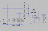
So in the simulation I calibrated the feedback resistor to give correct values on the highest current shunt, and it's linear when the current is changed, but when the other shunts are tried the voltage across the shunt, and the output voltage get more inaccurate as the shunt value is increased. Just tried a different amp, LT1012, same sort of error.
 

Attachments

  • summing.png
    summing.png
    8.2 KB · Views: 145
  • summing.asc
    2.4 KB · Views: 129
Could opamp input current flowing through the highest value shunt (5R) give a significant voltage drop?

The bias current is negligible, but the current in the feedback resistor is 2μA - this could account for it, and in fact most of it does flow though the input resistor. How on earth do I compensate for that then?
 
I used the LT1001 because it's the first one on the list. But surely for a true summing amp the error would be the same for all inputs, so it wouldn't make any difference? Even a 741 should be able to do this?

....................
The offset is the same for all inputs but each input amplifies the offset by a gain of 1+500k/10k = 51 at the output giving a total output offset gain of 51 * 4 = 204.

The bias current is negligible, but the current in the feedback resistor is 2μA - this could account for it, and in fact most of it does flow though the input resistor. How on earth do I compensate for that then?

2μA through any of the shunt resistors has negligible effect on the shunt voltage.
 
How accurate do you need the measurement to be? The error you mention back in post #7 of this thread is off less than 0.01% of the 1V nominal.
 
Ideally I'd like it to be within 1μV or better when it reaches the ADC - so as far as the output from the summing amp is concerned that would be within, er, 400nV. The trouble is, every stage introduces some kind of error, and whilst I hope they cancel out, they are just as likely to add. So I want to understand every error so I can minimise it. As I will have no standard against which to calibrate this beyond what I can build (unless I can find a friendly owner of something!) my options are more restricted. My budget is practically non-existent, which brings it's own limitations. The 95μV error in post #7 is just too great. It wouldn't be so bad if all the shunts produced the same % error. Thinking about it, it's a moot point anyway since I'll have to trim each input resistor. Still cheaper than using relays though and ultimately more accurate.
 
Ideally I'd like it to be within 1μV or better when it reaches the ADC -

Which ADC type are you using that resolves to 1uVolt,???
 
It's a LTC2415 24bit delta-sigma ADC. Linear say it can resolve 100nV. With a 5v reference it should resolve 298nV, but I'm not using the LSB unless I change the design again, so it's approximately 1μV for me. I've been designing around using a 5v reference, but I'm keeping my options open in that department.

I'd like to keep open the possibility of building these for other people, so I've got this kind of conflict of interest in "I'm the only person who will ever have to deal with this so it doesn't matter what quirks and tweaks it has or how long it takes to set up" and "if I build them for other people, it has to be a design consideration" So I'm considering this as Pixie MK1, a kind of quasi-prototype.

Of course, I could have done my sums wrong...
 
Status
Not open for further replies.

Latest threads

New Articles From Microcontroller Tips

Back
Top