Continue to Site

Welcome to our site!

Electro Tech is an online community (with over 170,000 members) who enjoy talking about and building electronic circuits, projects and gadgets. To participate you need to register. Registration is free. Click here to register now.

  • Welcome to our site! Electro Tech is an online community (with over 170,000 members) who enjoy talking about and building electronic circuits, projects and gadgets. To participate you need to register. Registration is free. Click here to register now.

Subwoofer psu repair

Status
Not open for further replies.

StudentSA

Member
Good Day,

I hope I can find some assistance with the repair of a KEF KUBE-2 Subwoofer circuit board.

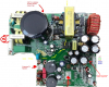
When taken apart I found two boards linked via two connectors. The top board held the audio input,volume control,crossover control knobs. I assume this top board is used to prepare the audio signal for injection into the amplifier board via one of the connectors. The other connector head appears to pass power to this top board and has 5 pins labled (+18,GND,-18,MODE,AGND).

In order to find which board is faulty I applied the +18,GND,-18 to the top board and the power LED came on as normal. So I decided that the issue must lay in the bottom (PSU and AMP) board.

When I apply AC to the bottom board, get 230V at the Full Wave Bridge Rectifier and 300V DC as the filter cap.

I also found that the power supply header for the top board is putting out 14-16V from the +18V pin and close to zero from the -18V pin.

I am having trouble understanding how the PSU board is creating this 18,-18 volt supply from the 300V DC.

Please could you advise what I could check next.

Top of Board
**broken link removed**

Thanks,
StudentSA
 
Last edited:
I am having trouble understanding how the PSU board is creating this 18,-18 volt supply from the 300V DC.

It's a switch-mode PSU, the large yellow rectangle at the top is the main transformer, the smaller one below is probably the standby transformer - the standby 'may' be working (giving you the +ve supply for the preamp) but not the main supply.

Switch-mode supplies are quite tricky to repair, and there's also a high danger of electric shock because much of it is live to the mains, and the large capacitors is charged to full rectified mains (340V over here).
 
Thanks Nigel,

The unit is extremely expensive to replace, thus the attempt at repair. I thought it may be a SMPS, however, I could not locate a SMPS "IC", I thought generally SMPS are built around a SMPS "driver" IC, I'll do more research into this.

Could you suggest where I could locate the datasheet for this transformer? as the numbers on top does not yield any search results. It has 5 pins on the big CAP side and 6 on the other.

I intend to check if the signals on each side of the transformer are as expected... I guess I first need to find out what is "expected"
 
Thanks Nigel,

The unit is extremely expensive to replace, thus the attempt at repair. I thought it may be a SMPS, however, I could not locate a SMPS "IC", I thought generally SMPS are built around a SMPS "driver" IC, I'll do more research into this.

They don't always use IC's, lower spec ones often are quite crude.

Could you suggest where I could locate the datasheet for this transformer? as the numbers on top does not yield any search results. It has 5 pins on the big CAP side and 6 on the other.

You won't find one, such transformers are almost always custom made (at least in my experience), and certainly so in this case.

I intend to check if the signals on each side of the transformer are as expected... I guess I first need to find out what is "expected"

The main primary winding will have full rectified mains 'square' pulses on it, the secondaries the same pulses, but smaller, depending on their required voltages.

For a start make sure you have full rectified mains across the big cap.

It would probably be a good idea to draw out the circuit of the primary side, so you can understand what's happening.
 
Thanks again Nigel,

I was mistaken, The small 8 pin smd chip on the bottom of the board is a "PWM Current Mode Controller" made by ON Semiconductor (NCP1203). My fiddling thus far has indicated that we have full rectified voltage on the primary cap (320V on DMM).


An observation that I made was that the "+18V" line does have a 15V signal and the "-18V" line measures zero. Does the fact that there is a 15V signal not imply that the primary is okay and the fault must certainly lay on the secondary side?

Kind Regards,
Umar
 
Thanks again Nigel,

I was mistaken, The small 8 pin smd chip on the bottom of the board is a "PWM Current Mode Controller" made by ON Semiconductor (NCP1203). My fiddling thus far has indicated that we have full rectified voltage on the primary cap (320V on DMM).


An observation that I made was that the "+18V" line does have a 15V signal and the "-18V" line measures zero. Does the fact that there is a 15V signal not imply that the primary is okay and the fault must certainly lay on the secondary side?

It would be EXCEEDINGLY rare to lose just one secondary voltage on a SMPSU, MUCH more likely (as I suggested earlier) is that the +15V comes from the standby PSU (the much smaller SM transformer).
 
chck the resistor on wat to -18V connector.
it appears to have burnt. i marked it with red arrow on the png attached.
 

Attachments

  • suspect burnt resistor.PNG
    suspect burnt resistor.PNG
    1.2 MB · Views: 1,587
Hi Guys,

Another observation is that the Transil Diode (1.5KE200A UniDirectional) (as shown in the green circle on the top view) is getting extremely hot(It burnt my finger). Could it be faulty? and if so how can I test it(I have never used a Transil before).

@Sarma, I believe those components are inductors as they are marked L503 and L504 I have swapped them and the result is still the same.

Regards,
StudentSA
 
Last edited:
Its difficult to test one of those without a high volatge power supply.
The fact its hot means either its faulty or there is a lot of high voltage noise on the supply (probably primary side).
Are you able to 'scope the gates or bases of the chopper transistors to see if the controller is trying to drive them?
 
1.5KE200A , having suffix A is unidirectional. We have to consider the wiring polarity depending on voltage there. please study the datasheet. if you had removed and placed back, perhaps a reverse connection is suspected. if there is a capacitor in series , better replace before tackling 1.5KE200A device.
 
Thanks dr pepper, I do have access to an oscilloscope but could you please help clarify a few things. I believe it wise to begin by ensuring the Primary side is working as expected.

I have picked up thus far that the primary is responsible for firstly providing the high voltage DC input to the transformer primary. I have thus tested a 320V DC on the main primary filter cap.
secondly, the 320V needs to be pulsed on the primary of the transformer to do this a PWM system/IC is used in conjunction with a power Mosfet(17N80C3). I should thus scope across the GATE to SOURCE an see if I have some pulses?

@sarma, component was replaced correctly.

Regards,
StudentSA
 
Exactly, be carefull at that volatge.

'scoping gate to drain will tell you if theres drive to the fet, and seeing if there is a 320 square wave on the source will tell you that the fet is probably ok (you wont get anything if the trans is open), also if the trans and rectifier is ok you'll get the characteristic ringing on the edges of the waveform.

Before you do that you could meter the fets, nake sure theres no shorts drain/source or gate/drain, source drain, and you can test the forward voltage of the inbuilt diode if it has one, also if you follow the tracks of the drain/source on the fets you'll find one end goes to the dc rail, and the other will go to the trans primary, you can also meter the primary, you'll probably only get a few ohms with a meter, its possible if the fets have shorted that the primary is open.
 
Hi,

Exactly, be carefull at that volatge.

I see why u mentioned this :D ... got a small Zzzzap while testing... but I'm all good.

Results are as follows... Initial tests with all components in place was no pulsing from the drive pin of the PWM and alot of heat from the transil.

I then traced the circuit and it seems like the transil serves a "protection" type role as it is not shown on the "typical application of the PWM IC" so I removed it from the circuit. On retesting I noticed now that the power mosfet was getting hot... so i removed that too. :D

With the mosfet and transil removed my heat issue was sorted :D and I started getting some reassuring results. I connected the scope ground to the ground of the main filter cap and scoped the mosfets "gate" pad and lo and behold there was a roughly 60khz 7V square wave. What does not make sense to me is that it was "pulse" like... so there would be a 7V 60khz signal then it would fall to ground then it would pulse up to 7v again etc. is this normal?

I made sure that the connections between the drain and source pads was as per the "typical application schematic". I just went off now to buy a few new Transils and MOSFETS. would it be safe to replace these or should I test something else to ensure that I don't blow the new parts?

Regards,
StudentSA
 
Last edited:
Hi,

Just an update, the replacing of the Transil and MOSFET did not help. I then began pulling out a bunch of components and testing.... and I believe I may have located the problem on the secondary... there are four surface mount diodes next to the main transformer... and two of them don't seem to function correctly... one is shorted and the other is passing current in the reverse direction.

My only issue is that the exact part is not readily available here in South Africa, I was thinking being a diode surely I could use something similar if not higher spec'd.

The original diodes are IDD09E60 (Infineon) please could someone assist me in finding a suitable replacement from za.rs-online.com

I had my eye on this DIODE/ but it is a dual diode is that a problem?

Kind Regards,
Umar
 
You should be able to sub the diodes, if you can look at the originals data sheet you'll need something with a similar reverse voltage rating, recovery time and current.

Well done for finding the issue, its not something anyone can do.
 
Just a final update.

I finally received the replacement diodes and managed to replace the existing four diodes with these. I then replaced any components I removed in the process and reassembled the board. I applied AC power and the measured output was +28 and -28 :D which is way better than the zero originally.

My only concern is that the silkscreen board label is +- 18V could this have been a mistake? or could I somehow have influenced the output voltage by replacing the diodes?

Once again thanks for all the help.

Regards,
StudentSA
 
Depends on how the supply is regulated, on a sub a few volts isnt much to worry about.
See if things are not getting mad hot after its been on a while.
 
Status
Not open for further replies.

Latest threads

New Articles From Microcontroller Tips

Back
Top