Continue to Site

Welcome to our site!

Electro Tech is an online community (with over 170,000 members) who enjoy talking about and building electronic circuits, projects and gadgets. To participate you need to register. Registration is free. Click here to register now.

  • Welcome to our site! Electro Tech is an online community (with over 170,000 members) who enjoy talking about and building electronic circuits, projects and gadgets. To participate you need to register. Registration is free. Click here to register now.

Subwoofer Amplifier Repair Help!?

Status
Not open for further replies.

Lymmie

New Member
Hey guys so...i come with a humble respect for the knowledge you all must have after perusing some of these forums. Im just a guy whos pretty poor and needs to fix his things rather than replace. I recently saved a nice acer monitor by replacing the capacitors that were bulged and leaking. Very blatantly obvious issue. Works great now! Fixed a small pyle stereo amplifier by replacing the potentiometers. One was very loose and it made scratching sounds when i adjusted the volume and one of the channels would cut out. Another obvious repair. This one however is not proving to be so obvious...

Its a dayton 120-ht 12" sub. Lil box with a plate amplifier on the back. Powers on. No protect light. It does play audio but theres a constant hum or noise playing through the sub at all times. If i adjust the gain the sub LOUDLY pops and crackles. This is with no source hooked up. I also tried different outlets thinking maybe it was a grounding issue as i have an ac unit on in this circuit but that also made no difference.

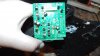
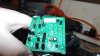
So i tore it apart. Pried apart the glued together wiring connections and disassembled everything. All capacitors look good. The potentiometers all feel tight and smoothe except one which was very rusty on the outside metal casing but again it feels tight and smooothe when turning it and thesolder points for the legs of the pot are all clean and rust free.

I am a complete novice if you guys havent noticed. I understand a bit from repairing alot of things on my jeep. Calibrating sensors and such. I love my piece of crap jeep as well. Look forward to getting to know you all and hope I can learn some stuff and get my bass back. I MISS BASS SO MUCH! I can provide photos as well if that would help. =)
 
If i adjust the gain the sub LOUDLY pops and crackles. This is with no source hooked up.
if it's "during adjusting" then its the pot if there's none e.g. electronic adjust - the power(s) or their levels are are "not there" where they should (a bigger problem -- but i never fixed multiple tens of ampere devices)
does play audio but theres a constant hum or noise
that unfortunately goes better with the second v. - as either the supplies are "tired" or there some other faulty components that cause chaotic operation

i guess there're better chances for you to drop the question in to some audio forums
 
Thanks for the reply. Could try replacing that pot I guess for the funsies and see what kind of improvement that makes. If it is shorting out internally who knows what kind of noise that oculd introduce to the system. I was mostly here hoping for help in identifying parts i should look at and test procedures with a multimeter. The capacitors dont look bad and thats about all i know to look for. An audio forum generally isnt going to have the caliber of knowledge that comes with circuit board repair.
 
Could try replacing that pot I guess
if the pot is "weard off" it should have "isles" of normal op and like carbon mic. audio-reproduce your movement on
what's on web
https://www.overclock.net/t/939032/warning-dayton-subwoofers-recall-amp-recall
some about ?conventional? woofers (a schematic - as what to expect to find inside the "black box") by (https://www.diyaudio.com/forums/subwoofers/156244-budget-musical-sub-4.html) . . . rainy day neck pain i cut my go for now ...
 
Pot doesnt feel "weard off" It feels tight and it appears to work as long as its not in motion. If you twist it makes all kinds of noise. That being said it pops and jumps so violently that i fear it would damage the woofer if i continued testing. Can a pot be bad even if its range of motion still feels tight? Ive only just recently replaced pots for the first time and i knew it was bad because of those isles you spoke of. Most of it felt really loose but right at hte 12 o clock position on the volume knob i could get both the left and right channels to come on with a little mini stereo amplifier i have. But this is mono. It wont work like that. Anyways...im not sure what else to do here so i snapped some photos. Lemme know if anything jumps out at you?
DSCF1577.JPG
DSCF1579.JPG
DSCF1580.JPG
DSCF1583.JPG
DSCF1584.JPG
DSCF1585.JPG
DSCF1586.JPG
DSCF1587.JPG
DSCF1589.JPG
DSCF1592.JPG
DSCF1594.JPG
DSCF1595.JPG
 

Attachments

  • DSCF1596.JPG
    DSCF1596.JPG
    1 MB · Views: 340
  • DSCF1597.JPG
    DSCF1597.JPG
    1.1 MB · Views: 308
  • DSCF1598.JPG
    DSCF1598.JPG
    1.1 MB · Views: 273
  • DSCF1599.JPG
    DSCF1599.JPG
    1.1 MB · Views: 274
A leaky capacitor that's letting DC through the pot could cause the large noise and pops you observe when moving the pot.
(The pot wiper generates resistive noise as it moves and this is translated to a large AC noise if there is DC current going through the wiper.)
Follow the pot traces to see if there are any capacitors in series with the traces.
If so, you might try replacing those capacitor(s) (especially if they are electrolytic type).
 
Is that 50V 68000uF cap leaking around its base, or is it adhesive showing?
 
A leaky capacitor that's letting DC through the pot could cause the large noise and pops you observe when moving the pot.
(The pot wiper generates resistive noise as it moves and this is translated to a large AC noise if there is DC current going through the wiper.)
Follow the pot traces to see if there are any capacitors in series with the traces.
If so, you might try replacing those capacitor(s) (especially if they are electrolytic type).
Is that 50V 68000uF cap leaking around its base, or is it adhesive showing?
All capacitors look fine. No bulging that I saw. The two big 50v 68kuf caps...I dont know. They feel weird. Like a hollow plastic shell i can kinda squeeze it. Not hard like the smaller ones. The top is smoothe plastic not the alluminum cross section that usually bulges out. See the 2 blue wires and the black one coming off the transformer block? (dont know if thats what its actually called. Please call me out! Im here to learn.) Those also look real burnedand brown like that capacitor but i assume its glue. How can I check or rather what am i looking for? I dont believe ive ever encountered electrolytic fluid leaking out of a capacitor or would be it burns on the circuit board? Honestly im just going off of my imagination here. Thanks so much for your help guys.
 
Any capacitors connected to the pot would not likely be bulging or have any other obvious physical problems to indicate a failure.
Those capacitors can fail without any physical signs.

Measure the DC voltage across the noisy pot terminals. The voltage across any two terminals should be 0V.
If you measure any voltage then you likely have a bad cap somewhere in the circuit connected to the pot.

Do i want the amp plugged in and turned on for this test?
 
Do i want the amp plugged in and turned on for this test?
Of course.
How else would there be any voltage to measure?
 
would there be any voltage to measure?
yes but it (woofer) has the fets off the sink and the ?driver transistors? seems have broken at un mount or then there's a weird shadows

at undefined state it is not too safe to assume low power draw at "no signal input"

i'd suspend the repair until you've downloaded the datasheets for the industrial looking amplifiers and get some grasp what there is going on on the board

. . .

something similar looking
https://esquemaeletronico.blogspot.com.ee/2011/01/esquema-de-amplificador-com-90w-rms.html
100W-amplifier.gif
 
Last edited:
yes but it (woofer) has the fets off the sink and the ?driver transistors? seems have broken at un mount or then there's a weird shadows

Im sorry im having a bit of trouble understanding your message. Woofer has nothing to do with the fets. The fets are sandwidched between the circuit board and the steel plate using thermal paste as the conductor betweent he fet and the plate. I see driver transistors look like the chips called bd and tip in that picture you posted. You said the seams have seperated? Ill take a look and see if that is the case.

I hooked all wires up other than the two leads going to the subwoofer. THe subwoofer leads gave off 3.9v at all times even with no source plugged in. I hooked up to the pots several various poles and tested for voltage and maneuvered the pot through its cycles and never got voltage spikes above 0.05. Most of the time it was 0
 
The fets are sandwidched between the circuit board and the steel plate using thermal paste as the conductor betweent he fet and the plate. I see driver transistors look like the chips called bd and tip in that picture you posted.
!!! that picture is like a best guess what there might be on your board
!!! be aware not taking any suggestions here as True by default . . . i see the sub-woofer (**broken link removed**) first time ever (not a joke)
-- however similar things (such as audio amplifier stages) can be completed/made in a counted no. of ways - so the circuits appear alike (as functionally as visually) -- can be used as a debugging aid of your particular "mod(iffication)"

I hooked all wires up other than the two leads going to the subwoofer. THe subwoofer leads gave off 3.9v at all times even with no source plugged in. I hooked up to the pots several various poles and tested for voltage and maneuvered the pot through its cycles and never got voltage spikes above 0.05. Most of the time it was 0
. . . my best guess is no ~AC/audio input -- this is what it should be
(((( rushing things /// however if you put in some 25µV to 2.5mV sine at the central band frequency of the woofer and it gets out distorted . . . then there's something wrong at somewhere along the signal path )))) "Specifications****: • Power output: 120 watts RMS • Frequency response: 25-140 Hz • Box design: Ported • Inputs: RCA line level & speaker level • Outputs: Speaker level • Crossover frequency control: Continuously variable from 40 Hz to 140 Hz @ 12 dB/octave • Phase switch • Auto on/off • Power requirements: 120 VAC, 60 Hz"
 
Last edited:
? you quiet i supose scratching the layout schematic from your PCB-s is a way to go ... they only look complex -- as long as you track the traces a scetch a schematic and optimize it's layout ...
__________________________
the SBS20 case - just for illustrating ::
co-A55M.gif SBS20-aps.gif
 
Have brought amplifiers from storage and the adjustment trimmer potentiometer would make a scratch with some impressive pulsing through the speakers. Some times just casually turning the trimmer itself from left stop to right stop some turns would clear the wiper within the potentiometer with power not applied to the amp after the noise discovery. Would usually take quite a few turns to clear up some issues over others with lighter corrosion that would take less turns to clear.

Tho some were quite damaged on the carbon trace that had pits that just flaked off resulting in resistance jumps that never went away. Taking them apart would often brake the press tabs leaving the carbon rings board material to fall out constantly or self shift with vibration.

Those op amps on the adjuster board look to be JRC, Japan Radio Corporation. JRC4558. Both trimmer potentiometer are 50K Ohms each, 3 total. 2 with jumper beam between them (C 50K), one solo (A 50K). Lettering is likely tolerance rating.
 
you think acupuncture is worth to try o_O
wahtewer the case -- translating the esoteric channelings into human language would be something - power/signal paths blocked - the good question is which/where
 
Last edited:
Should work Better than yump bump thump. I have tried it (acupuncture)! for a head ache. And no it did not work either. :(
 
Some times just casually turning the trimmer itself from left stop to right stop some turns would clear the wiper within the potentiometer with power not applied to the amp after the noise discovery. Would usually take quite a few turns to clear up some issues over others with lighter corrosion that would take less turns to clear.
(My emphasis).
I have "cleared" many, many pots (on all sorts of gear) using this method, especially infrequently used pots. As GromTag notes, with power OFF, rotate the shaft back and forth, stop to stop at least 10 Xs or more. It cleans/clears the wiper surface as well as the carbon path.
 
Status
Not open for further replies.

Latest threads

New Articles From Microcontroller Tips

Back
Top