Continue to Site

Welcome to our site!

Electro Tech is an online community (with over 170,000 members) who enjoy talking about and building electronic circuits, projects and gadgets. To participate you need to register. Registration is free. Click here to register now.

  • Welcome to our site! Electro Tech is an online community (with over 170,000 members) who enjoy talking about and building electronic circuits, projects and gadgets. To participate you need to register. Registration is free. Click here to register now.

Struggling to complete a circuit design and require help with Op-amps...please!

Status
Not open for further replies.
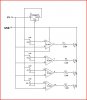
I am struggling to design a 9v battery tester for university. It must use 4 LED's to indicate the voltage level of the battery. So far I have a working circuit on multisim using 4 resistors in parallel with eachother, each with an LED in series.

This works in theory as the different resistors limit the voltage to the LEDs, thus indicating the voltage.

However, in practice, the LED's can only support a maximum current of 5mA whilst the circuit is running much higher.

I think I need to incorporate an (or 4) inverting op-amps to reduce the current so as not to blow the LED's. But I'm not so sure and don't know how to do so effectively

I also believe I ought to utilise diodes to ensure I do not get back EMF but am not 100% certain.

Any help anybody could offer would be greatly appreciated, although I'm not looking for just the solution in diagram form I would greatly appreciate an explanation of why things go where so I can understand it for next time!

In the meantime I shall attempt to figure it out via trial and error on multisim.

Many thanks in advance,

Alex


____________________________________________________________________

How did i miss spell my username?! Insert : "EngineersDoItTilItHertz"
 
Last edited:
Post the schematic of the circuit you're trying to build. There could be any number of reasons why it's not working.

Dave M
 
I have not put much thought into this, and it is untested, but one simple way would be something like in this schematic.

You would need to adjust each pot to set the voltage its led turned on at.

I am not prepared to write a how it works as you should be able to figure that out as it is your project not mine.

With luck you might get other more advanced ideas, but this should give you a starting point.

Pete.
 

Attachments

  • opamp led switch.JPG
    opamp led switch.JPG
    41.8 KB · Views: 324
Last edited:
This works in theory as the different resistors limit the voltage to the LEDs, thus indicating the voltage.

However, in practice, the LED's can only support a maximum current of 5mA whilst the circuit is running much higher.
I don't understand what you mean by the second sentence. What "circuit" is running much higher?
 
I have not put much thought into this, and it is untested, but one simple way would be something like in this schematic.

You would need to adjust each pot to set the voltage its led turned on at.

I am not prepared to write a how it works as you should be able to figure that out as it is your project not mine.

With luck you might get other more advanced ideas, but this should give you a starting point.

Pete.

Pete,
Your circuit is similar to the ICs:-

LM3914 & LM3915.

The 3914 is linear & the 3915 is a logarithmetic.
 
Last edited:
I dont know Len, i have never used those chips.

I just threw together the circuit as a starting point for him to start at.

Opamps can be very confusing to work with and thought just a very basic circuit would perhaps help here, as the student appears to have no idea of how to use an opamp or the function of them.

I still have my senior moments with them as well.

Pete.
 
That's not a good circuit to drive LEDs. Opamps are usually poor choices to drive any load that requires any appreciable current. Generally speaking, opamps are more comfortable driving loads of 2K or higher. A comparator with open collector outp[uts would be a better choice in your circuit. LM339 is an example. Using a comparator would still require a voltage divider at each input.
A much better choice would be the LM3914 LED driver IC. It's available from Digikey (www.digikey.com). The datasheet is here https://www.electro-tech-online.com/custompdfs/2011/01/LM3914.pdf. You just set up one voltage divider at the input and connect the LEDs to each output. It's a much better choice than using opamps or comparators.

Dave M
 
No disrespect intended but rather than pissing in the wind with quotes how about a schematic we can all follow.

A schematic speaks a thousand words,

Pete.
 
So far I have a working circuit on multisim using 4 resistors in parallel with eachother, each with an LED in series. This works in theory as the different resistors limit the voltage to the LEDs, thus indicating the voltage.
That is where you are wrong. A resistor in series with an LED limits its current, not its voltage.
Your LEDs will all turn on at almost the same voltage but the ones with the lower resistance value will have more current and therefore will be brighter.
You need to limit the voltage with a pot like was shown, or with two resistors in a voltage divider that drives the LED driver circuit.
The circuit shown will blow up the opamps because their (-) input voltage is higher than their 5V supply voltage. They should have a voltage divider.

An inductor has a back EMF, not an LED.
 
Status
Not open for further replies.

Latest threads

New Articles From Microcontroller Tips

Back
Top