Continue to Site

Welcome to our site!

Electro Tech is an online community (with over 170,000 members) who enjoy talking about and building electronic circuits, projects and gadgets. To participate you need to register. Registration is free. Click here to register now.

  • Welcome to our site! Electro Tech is an online community (with over 170,000 members) who enjoy talking about and building electronic circuits, projects and gadgets. To participate you need to register. Registration is free. Click here to register now.

Strange behaviour on pic ADc input

Status
Not open for further replies.

Thunderchild

New Member
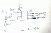
I've designed and (alegedly) built a pic (12F615) based battery monitor circuit for car/bike/you name it lead acid battery. I'm using the ADC converter to convert the battery's voltage (also the supply power) to a 10 bit binary number with which the program determines which leds light,
I've used a 2.2+1 K potential devider to convert the 0-16 volt range to 0-5 volt range but i have a small problem, I'm only getting 0.1 volt from this when powering the circuit from 12 volts and i should be getting about 3.75 volts, whats going on ???

strange thing is i had this working on a breadbord with a 10 K pot !!! (well i have changed from ADC input 0 to 3) perhaps I got some register setting wrong ? it did behave eratically on the pot after that but i think the pot is brocken....
 
ah ! haven't got one, as for the pic input and the resistors its simple, 2.2 K from Vcc to pin 3 of 12F615, 1 K from GND to pin 3 of 12F615, i'm gettng 0.1 v instead of 3.75volts on pin 3 of the 12F615
 
If you do not even have a schematic, perhaps you do not really know what you have built. Pencil, paper, and a scanner or camera will do.
 
Building upon what Blueroom has said, some PIC 12's especially with the low pin count need certian functions to be switched off as they are "multiplexed". I had a similar prob with a 12F510, you can turn on certain ADC pins or all of them, you really need to read the datasheet thouroughly with the 12F's, it took me 3 or 4 reads to realise this, and it's not uncommon. For example 2 pins may be the timer pins also, so you will need to switch the timers off, etc, you will need to look up the pin function precedence.
 
I' try and get a scematic up later but it does not really help in this issue, I think i know what I built, I'll have a thorough read of the datasheet today see if I can spot anything
 
schematic attached. according to the data sheet the AN3/GP4 pin is input only.... I'll have to look at all other functions

could it be that the "weak pull ups" need disabling ? that might account for this going haywire, its the WPU register
 

Attachments

  • _IGP7222.gif
    _IGP7222.gif
    36.9 KB · Views: 1,069
Last edited:
Apparantly setting inputs will disable everything else so i'm very confused, this worked with the input on AN0
program is basic

Code:
dim V as word                        ' Declarations section

main:                                ' Main program

 TRISIO  = %00001000                 ' set GP4 as input GP0,1,3 as output
 ANSEL   = %00001000                 ' GP ,1,2,3,5 as digital, GP4 as analog
 
  'ADON0 ADC register setup
  
 ADCON0  = %10001101
                                     'R justify result
                                     'use VDD as Vreff
                                     'select channel 3
                                     'enable ADC

                                     
GPIO = 0                       ' reset all outputs

run:
delay_ms(10)
V = ADC_read(3)                ' check battery voltage from AN3 pin

if V < 700 then GPIO.2 = 1  'if V is under 11 V
   else GPIO.2 = 0 end if                   'the red warning led will stay on

if (V < 920) and (V > 703) then GPIO.0 = 1
   else GPIO.0 = 0 end if     'if V is under 14.4 V then lightup red led
   
if V > 780 then GPIO.1 = 1
   else GPIO.1 = 0 end if     'if V is over 12.2 V then lightup green led
   
   
' warning level check and flash routine which will be locked into if over volt
' occurs

    if V > 990 then
     GPIO = 0
       Flash:
         GPIO.2 = 1
         delay_ms(300)
         GPIO.2 = 0
         delay_ms(400)
       goto Flash
          else
          goto run
        end if
                             'repaeat cycle

end.
 
Last edited:
hi,
I dont use that form of Basic, but I have downloaded the 12F615 data and I will check thru your program.

I assume that with your 2.2K and 1K resistor divider you do get 3.75V when the divider is NOT connected to the PIC.?
 
are there other forms of basic ? I find the mikroe one a bit tedious,
I'll have a check tonight when i get home with the pic out of the socket
 
any other free ones out there ? I'd rather pic my best one before getting headlong into leaning the mikroe one, at the rate I'm going i might as well mean assembler !
 
If the program works on AN0 and not AN3, then you have to look at the other pin functions and registers affecting the AN3 pin, like Wilksey has mentioned.

The compiler most likely has a initialization routine that sets registers in a predetermined way. The only way to see these ,is to look at the assembler. Then its a trudge through the data sheet to make sure the comparator, clkout, timer1 gate etc. are not being enabled in their respective registers.

If you are using the internal oscillator, make sure the config in assembly is either _INTRC_OSC_NOCLKOUT or perhaps _INTOSCIO?

GCBasic will do the job, the price is right, and it has come a long way in the last couple of years.
 
its very odd i just half plugged the pic into the circuit and the orange light came on which is correct, at another time thought the Vdd was 1 V !! this is very odd, i have examined the board with a magnifying glass and can't see any trace of short circuit
 
Take a look at this line of code:
Code:
TRISIO  = %00001000                 ' set GP4 as input GP0,1,3 as output
If trying to set GP4 (i.e AN3) as input, GP3 is always 1, TRISIO should be:
Code:
TRISIO  = %00011000                 ' set GP3,4 as input GP0,1,2 as output
 
Last edited:
hm you have a point, so you say I'm confusing AN3 with GPIO3 ? sounds like the answer, adding to that that bit "0" is the first digit I'm just not seeing it am I... I'll try it and let ya know
 
Your perfectly right nick thank you so much its such a silly mistake but its an easy one to make (well thats my exscuse :D)
 
Status
Not open for further replies.

Latest threads

New Articles From Microcontroller Tips

Back
Top