When I use a USART in a PIC, the choice is 1 or 2 stop bits.
However, in the SiRF reference manual, this is shown:-
That seems to show that there is a choice of 0 or 1 stop bits.
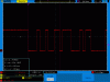
I don't see how 0 stop bits would work. Also, on the two types of GPS modules that I am using, there seem to be two stop bits. In the image, you can see the $ and G from the start of a GPS string, and there is a high period of two bits at the end of each.
Can anyone explain why the number of stop bits seems wrong?
However, in the SiRF reference manual, this is shown:-
Code:
Message ID	$PSRF100	PSRF100 protocol header
Protocol    	0             	0=SiRF binary, 1=NMEA
Baud         	9600        	1200, 2400, 4800, 9600, 19200, 38400, 57600, and 115200
DataBits   	8               8,7
StopBits   	1              	0,1
Parity        	0               0=None, 1=Odd, 2=Even
Checksum	*0C
<CR> <LF>               	End of message termination
That seems to show that there is a choice of 0 or 1 stop bits.
I don't see how 0 stop bits would work. Also, on the two types of GPS modules that I am using, there seem to be two stop bits. In the image, you can see the $ and G from the start of a GPS string, and there is a high period of two bits at the end of each.
Can anyone explain why the number of stop bits seems wrong?