Continue to Site

Welcome to our site!

Electro Tech is an online community (with over 170,000 members) who enjoy talking about and building electronic circuits, projects and gadgets. To participate you need to register. Registration is free. Click here to register now.

  • Welcome to our site! Electro Tech is an online community (with over 170,000 members) who enjoy talking about and building electronic circuits, projects and gadgets. To participate you need to register. Registration is free. Click here to register now.

STM8 resets while switching a relay through npn transistor

Status
Not open for further replies.

Sana1234

New Member
Hi,
I have Design a Relays Based AC Switch Board using STM8s003 and ESP01. When I connect even a small resistive load then the controller resets during relays switching.... i dont know whether where is the problem in my design?

>>The Board is working fine when there is no AC (220v) load Connected; but with AC Load Connected, then MCU resets during switching
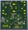
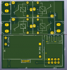
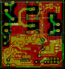
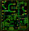
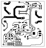
Same type of switch boards are available online containing stm8 but i havent experienced these boards regarding such an issue and i also i dont know about there design.... my schematic and PCB is attached.
kindly tell me where my design need modification or correction...
Thanks
 

Attachments

  • pcb.PNG
    pcb.PNG
    14.4 KB · Views: 281
  • sch.pdf
    106.2 KB · Views: 272
Thanks Ian Rogar for replying....
Ground bouncing might be the reason but is it possible in my design that ground bouncing occurs only when AC load is connected to ground?? Without AC loads the relays Switch Accurately tested 100 times each relay without a single reset of MCU....
 
Without the AC loads the current spikes on the relay are not as much... I did this recently, I had to use a ground plane and lots of decoupling caps... I had 0.1uf's and 100uf's... The regulator is close to the relay as well... This could also get noise from the AC loading... Have you a scope so you can see what's going on when the micro resets??
 
This is a common issue. Additionally you can look at your code. if it is RMW(Read Modify Write) you can have this type of trouble also... If there is an option to write to LATx over PORTx then use LATx. If there isn't a LATx option then make modifications to a temp variable, and move the entire variable to the Port rather than one bit at a time instructions like BCF or BSF
 
It is hard to see what is happening but:
It looks like the schematic and the board the same. (C2,3,6,7 are next to each other)
You need C2 right at U6 pins 1-3, C3 at U6 1-2. C6 at U10 7-9, C5 at U10 7-8.
I do not have time to look but C4 needs to be at U10. If the wire length is long you will get a reset.
As Ian said; your grounds are very bad.
1552320182103.png

What CAD software are you using?
 
ok thank you all for your suggestions....
let use a ground, decoupling caps....(lan) and relocate the caps...(sonsimpson)
and Mr. Beau could you please explain the terms RMW and LATx or share some links about their details..... thanks:)
 
I don not know KiCad but I think it can do area fills or ground planes.
1552330695788.png

Not my board. See how much ground copper there is.
How are you getting your board made? Most places do not have a lower cost for single sided. Or at least check out the price for double sided.
 
i have designed single sided PCB to be cost effective... through hole plating is very much expensive where ever i have access to. wont it be useful if i use ground plating in sigle side PCB? or i must use double side copper board?? please suggest what would be better?? could you please tell me the proper way of ground plating or share some links?? Thanks:)
 
Last edited:
Hi all!
I have Modified my Schematic and PCB design mostly according to the points mentioned in post# 4 and 6.....Some files are attached, kindly analyse and comment on the modifications specially ground plan....so that i could fabricate and test it ..... thanks..
 

Attachments

  • 3d-bot.PNG
    3d-bot.PNG
    45.9 KB · Views: 273
  • 3d-top.PNG
    3d-top.PNG
    36.4 KB · Views: 259
  • GND-plane-both-on-top-and-bot.PNG
    GND-plane-both-on-top-and-bot.PNG
    42.1 KB · Views: 266
  • power-20mil.PNG
    power-20mil.PNG
    43 KB · Views: 273
  • sch.PNG
    sch.PNG
    13.6 KB · Views: 256
Ground bounce is a common problem, and so is brown-out (low input power) when switching heavy loads. Using the same Vin for the relays and the regulator that feeds the micro is not a good idea unless you use a lot of bulk capacitance at the input of the regulator as well as a modest amount of capacitance (10uF to 100uF) at the output.

You also want some low ESR capacitors (like tantalums) on input and output to deal with fast transients. 10uF on the input and 1uF on the output are very common.

And as the others have mentioned, a solid ground is important. A single point ground is best, and a solid ground plane is good. Also keep the relay power lines and loops short as possible, and keep them as far away from the micro and its power and reset lines. You don't want the relay power loops generating large EMF signals to the micro's connections.
 
Status
Not open for further replies.

Latest threads

New Articles From Microcontroller Tips

Back
Top