Continue to Site

Welcome to our site!

Electro Tech is an online community (with over 170,000 members) who enjoy talking about and building electronic circuits, projects and gadgets. To participate you need to register. Registration is free. Click here to register now.

  • Welcome to our site! Electro Tech is an online community (with over 170,000 members) who enjoy talking about and building electronic circuits, projects and gadgets. To participate you need to register. Registration is free. Click here to register now.

Stepper motor wiring?

Status
Not open for further replies.

things

New Member
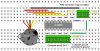
I have a stepper motor here from a light, so it was originally used to spin a wheel with the gobo's on it. I am trying to figure out how to drive the stepper, and cant find any specifications on it.

It has 5 wires, being Black, Yellow, Orange, Red and Brown.

I've measured the resistance between each of these wires, and I cant figure out which is common and how i'd wire this?!

**broken link removed**

red-brown = 57.6 ohm
red-yellow = 59 ohm
red-orange = 58.4 ohm
red-black = 58 ohm
brown-yellow = 116 ohm
brown-orange = 115.7 ohm
brown-black = 115.3 ohm
yellow-orange = 116 ohm
yellow-black = 116.3 ohm
orange-black = 115.9 ohm

EDIT: OK, the red wire seems to be common, any idea's on what voltage it'd need?

Any advice is appreciated :)
 
Last edited:
Seems to be a size 23 unipolar single stack, cheap can style. It would be about 3w per phase, maybe 4 but personally i'd keep it at 3. It will still get toasty in continuous use.

So at 58 ohms;
12v 206mA 2.48w
14v 241mA 3.37w
16v 275mA 4.41w

Looks like a handy 12 volt(ish) motor.

You can drive it direct from a ULN2003 (7x darlington 16pin) chip, they are rated for 500mA.

The magnetics in that can style package are pretty poor and they dont have a huge amount of holding torque, and its almost certainly specced for full-wave "2 phase on" for normal operation.

My web page has an old page on measuring stepper motor torque;
Measuring stepper motors
 
Hi things,

I doubt your results a bit.

A bipolar motor with two center taps connected to one wire must have four identical resistance values (+/- tolerance) from the center tap to each outer end of the two coils. Both outer ends must logically have the double resistance.

They are not connected to any other wire within the motor.

You measured four times ~58Ω and six times ~116Ω, which makes no sense for me.

I agree that red must be the common center tap connection though.

Attached is a schematic diagram of a bipolar stepper motor.

I suggest to use the red wire for center and try all other connections to see what happens.

Boncuk
 

Attachments

  • BIPOLAR.gif
    BIPOLAR.gif
    5.2 KB · Views: 3,349
Hi,

Isnt that a unipolar motor? The way to drive it is to connect the red
wire to V+ and connect the other four wires to the collectors of
some NPN transistors that are driven with a unipolar driver.

This kind of motor is problematic in that you can only use a unipolar driver.
If you try to run it as bipolar, a problem will occur because the two center
taps are connected together. More often a unipolar has six wires, where
the two center taps are independent, and that gives you the option of
driving it with a bipolar driver (at reduced power).

I would guess the current to be 500ma, but you could tell if you run it at
500ma and it gets too hot then you would have to reduce current.
You could also compare to other stepper motors of the same size and
see if you can figure out the power rating from there.

From your limited measurements that schematic that Boncuk drew up looks
accurate so i'll repeat it here...
 

Attachments

  • BIPOLAR.gif
    BIPOLAR.gif
    5.2 KB · Views: 745
Last edited:
Hi,

With 5 wires, it should be unipolar. A part number would help to find specs. Anway, It look the same as some small printer motors. If it is the same it could be rated at 24 volts. But if you try to run it at 24 volts, It will probably overheat because those motors need a sophisticated driver to keep them cool.


You can drive it with the circuit below. The computer pins refer to the parallel port pins. Note that it is the black wire that is the common on that circuit. Using 12 volts should not harm your motor and it will not heat so much. If you omit the freewheel diodes connection (pin 10 of the IC), the motor will probably run better.

Alain

breadboard-uln2803et-step-jpg.30993
 

Attachments

  • BreadBoard ULN2803et step.jpg
    BreadBoard ULN2803et step.jpg
    96 KB · Views: 34,441
Last edited:
Isnt that a unipolar motor?

Of course it's a unipolar motor, the same I added as a schematic.

Blame it on my language barrier. :)

I sometimes mix up unipolar and bipolar.

Boncuk
 
Hi again,


Oh ok sure, not a problem :)
I just wanted to make sure we all were talking about the same thing so that
the correct driver could be chosen. It doesnt work to use a bipolar driver
on a unipolar motor unless that motor has two separate coils, not connected
by a common lead like this one does.

BTW AlainB:
I dont think you can use the freewheeling diodes that way because when one side of
the coil is pulled to ground via a transistor collector the other side goes to +24v, which
is two times the supply voltage. This will cause a huge current to flow.
The freewheeling diodes for this circuit would have to go to ground, with cathode on
the outputs of the darlington array and anode to ground.
Perhaps they make an array that is built with the diodes the other way.
 
Last edited:
There appears to be a paper label on the side of that motor. Why not look up the motor's spec sheet?

A 6-wire unipolar motor can generally be connected as bipolar by ignoring the middle wires. I'm not sure about 5-wire though, that might depend on the controller. A 4-wire "bipolar" cannot be connected as unipolar since it lacks the center connections.

Unipolar will only yield 70% of the torque of bipolar, but bipolar is a more complicated controller.
 
Hi,

There is plenty of drawing online illustrating the use of the ULN2803. I never saw it plugged otherwise., I mean for the freewheel diodes. "The freewheeling diode(s) in the ULN2803 are there to clamp the motor noise/reverse current" do I read somewhere. But I know that it is better not to use them. The motor will run smoother and, after hours of usage, I never notice any bad effect of not using them:

YouTube - 3 axis CNC for PCB drilling

I suggested to use this chip for the OP motor and I am pretty sure that it will work. But the chip will probably heat up and will need cooling.

Alain
 
Last edited:
24v??? 500mA???? :eek:

Did nobody read my post? Dunno why i bother sometimes.

The proper way to use the freewheeling diode pin on a ULN chip with a unipolar stepper is to connect the pin through a RC snubber to V+ or through a reversed zener diode to V+. With a 12v 200mA motor like the one shown, the diode pin is probably not needed (as AlainB said).


Hi,


Why the question marks after 24v ???
 
Because I already said in my first post that stepper motor package is rated at around 3 watts per phase.

Regardless of manufacturer or datasheet, stepper motors are rated at the watts/phase for package dissipation. If you have worked with most of the packages for enough years you can look at a stepper, see what package it is, and know what the phase watts are based on other motors you have worked with in that package.

Since we know the phases are 58 ohms, and I know that motor is somewehre around 3 watts per phase, the correct voltage/current per phase is about 12v/200mA.

Occasionally that package is derated to 2.5 watts or so, but it appears to be on a fair size alloy bracket so i'd try about 3 watts.

24v into 58 ohms would drive each phase at 12 watts!
 
Status
Not open for further replies.

Latest threads

New Articles From Microcontroller Tips

Back
Top