Continue to Site

Welcome to our site!

Electro Tech is an online community (with over 170,000 members) who enjoy talking about and building electronic circuits, projects and gadgets. To participate you need to register. Registration is free. Click here to register now.

  • Welcome to our site! Electro Tech is an online community (with over 170,000 members) who enjoy talking about and building electronic circuits, projects and gadgets. To participate you need to register. Registration is free. Click here to register now.

? "Standard" offset nulling circuit for comparators

Status
Not open for further replies.

ci139

Active Member
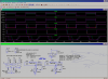
i almost dumped the chips as incapable for low voltage operation
although the d/s -s of LM311 and LT1011 claim the op.-g range should be 3.5÷30V and 3.0÷36V respectively

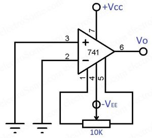
► at what condition the offset nulling should be done or is it only specific in-circuit ??? -- as it looks the output "zero" depends on supply voltage and OUTP.load values . . . input frequency . . .
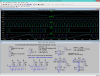
 

Attachments

  • LM311 - Test - 0101-mp.png
    LM311 - Test - 0101-mp.png
    34.2 KB · Views: 164
  • LM311 - Basic-Test - BB-0100.png
    LM311 - Basic-Test - BB-0100.png
    53.1 KB · Views: 157
Last edited:
a good coverage but does not exactly answer if there is any offset adjust std.-s
. . .
more finds the К554СА3
 

Attachments

  • LM311 - Basic-Test - BB-0100-q.png
    LM311 - Basic-Test - BB-0100-q.png
    52.6 KB · Views: 147
  • LM311 - Basic-Test - BB-0100-blc.png
    LM311 - Basic-Test - BB-0100-blc.png
    63.4 KB · Views: 150
Last edited:
self asking - self answering . . .
  • i guess these op amp circuits/methods can and somewhat be substituted for comparators
  • there seems not to be standard circuit / -configuration for DC input offset nulling
  • the basic level shift circuit modifications are there what are used for external offset adjustment (not inquired in original question but co-listed here)


,
. ,
. , .

. , . , . , .

.

related ::
 
Last edited:
about the removed SMPS commercial

those things have control elements built in
some of which are the voltage comparators

the person that attempts to design build the PSU or SMPS on it's own -- does that because he/she cannot find the suitable (functions/price/e.c. ...) unit on the market

the commercial actually pointed out the market shell that is not scanned by conventional western product search

there is always a possibility for one to save time / effort /and money -- by not going to "re-invent the bike" but accommodate the existing product while there is one avail ...

((i donno you guys must be eating something wrong - as you do one miss-evaluated decision by another))

Blatant advert removed by moderation.
 
Last edited by a moderator:
about the removed SMPS commercial
Around here we call it SPAM.
We moderators do our best to remove it quickly in order to keep the forums free from commercial advertising.

JimB
 
Do you notice that the opamp circuits shown have negative feedback so that they have a reasonably low voltage gain? Then the offset is amplified only by the fairly low gain and the adjustment is easy.
But a comparator has no negative feedback so it amplifies the offset voltage 200,000 times (LM339 and LM393) and it will be impossible to adjust an offset voltage null.

Why do you want to make an offset voltage null? The LM339 and LM393 comparators have a typical offset voltage of only 1mV or 2mV max.
 
buy an op amp with a lower offset voltage? surely the cost and hassle of timming a cheap op amp is negated by the extra cost of a good op amp in the first place
 
Why do you want to make an offset voltage null? The LM339 and LM393 comparators have a typical offset voltage of only 1mV or 2mV max.
actually i don't
what i want is the "best" setting/bias for comparator to act "most properly" e.g. if both inputs stay near each other - to be able to have a change at the output if theoretically there should be one - simple
notice that the opamp circuits shown have negative feedback so that they have a reasonably low voltage gain
50de77ccc0bebc6506d1f5dd440342803ec73d4c_128.gif
 
Last edited:
Do you notice that the opamp circuits shown have negative feedback so that they have a reasonably low voltage gain? Then the offset is amplified only by the fairly low gain and the adjustment is easy.
But a comparator has no negative feedback so it amplifies the offset voltage 200,000 times (LM339 and LM393) and it will be impossible to adjust an offset voltage null.

Why do you want to make an offset voltage null? The LM339 and LM393 comparators have a typical offset voltage of only 1mV or 2mV max.

Hi,

For a comparator it is more like input offset compensation rather than nulling, but the idea is the same. That is, to make the inputs appear to be actually equal with actually equal external input voltages (such as 0v but that's only one point). The reason for this is so that the comparator will trip at the more exact voltage level than if it had an offset.
For example, if we need a comparator to trip at 1.000v plus or minus 100uv then 0.001v input offset is too much.
A place where this might be important is in a flash ADC.
 
The OP is about comparators but then op amps' offset is discussed.
Find that just confusing.
 
Without hysteresis the extremely high gain of a comparator causes its output to swing back and forth with extreme swing when the inputs are near the trip voltage. It is caused by internal and external random noise. With hysteresis the output has a "snap action" caused by the positive feedback of the hysteresis.
 
The OP is about comparators but then op amps' offset is discussed.
Find that just confusing.


Hi,

Well both types of devices have input offset.
 
some tests (offset -- don't care assume near ideal Zero)
// the К554СА3 is a substitute for LT1011 or LM311
Update 2017-09-02 :: amazingly the LM311 substitute works - it shouldn't - so i yet have to get why how and what it does exactly . . . the bit easier is with TL082 as it does not have to step outside it's slew rate reach to follow that particular analog src. signal
 

Attachments

  • Random_OpAmp_0200.png
    Random_OpAmp_0200.png
    49.3 KB · Views: 139
  • Random_Slope~dct_0010.png
    Random_Slope~dct_0010.png
    55.9 KB · Views: 137
  • Random_Slope~dct_0011.png
    Random_Slope~dct_0011.png
    52.7 KB · Views: 128
Last edited:
LM311 - Test - 0110.png "External balancing" the K554CA3 (more realistic Spice model of the LM311) using something MAT03
////
. . . more correct v. with no balancing (can likely be defined using Op amp with similar input stage with similar biasing ? or LM311 with strong neg. feedback ?)
LM311 - Basic-Test - BB-0100-zjq(modified).png LM311 - Basic-Test - BB-0100-zjq2.png
 
Last edited:
Status
Not open for further replies.

Latest threads

New Articles From Microcontroller Tips

Back
Top