mechie
New Member
A simple bench PSU capable of :-
Approx. 5v to 15v output at 1A
Current limited from about 500mA to 1A (adjustable)
Circuit Operation
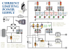
An error amplifier is formed from Tr1 and Tr2, wired as a differential amplifier (often called a long-tailed pair -- look at those collector leads). One input of this diff. amp is taken from the zener diode which provides a stable 4.7 volts, the other diff. amp input is a fraction of the output. Any difference between the two will cause the current through R3 to alter and so will alter the voltage across it and hence to the base of Tr3.
Tr3 and Tr4 are connected as a darlington pair, this produces a very high gain to aid stability of regulation. This darlington pair can be visualised as a single transistor connected in an 'emitter-follower' configuration, the emitter voltage will follow the base voltage (less the 1.2v required to forward bias the two base-emitter junctions), but with a much greater current capacity.
Current limiting is provided by Tr5 which will be forward biassed by a fraction of the voltage drop across the current sensing resistor, R5, set by Vr1. As the current through R5 increases so does the voltage dropped across it, this begins to bias Tr5 on and in so doing causes Tr3/Tr4 to be deprived of base current and so reduces the output voltage.
Tr4 needs a heatsink of at least 10 degrees C/Watt (10C / W) and R5 is expected to carry (1A * 4R) = 4 Watts, so it will need to be a 5W device or four 1R 1W devices in series, mount them on a peice of metal as they will get hot!
The transformer needs to be selected to suit your local mains voltage and provide between 15 v and 20 v out at 1A (thats 15 or 20VA, respectively).
As there is no current measurement built in to the unit, a useable scale could be marked around the potentiometer Vr1's knob such that a known current could be chosen in advance of connecting a load. To do this, connect an ammeter directly across the power supplie's output - this will instantly overload the supply and cause the current limiting to operate. Adjust Vr1 so that the ammeter displays 500mA and mark the knob's position. Repeat the procedure for 600mA, etc. ## DON'T keep the supply shorted for too long as Tr4 and R5 will soon get hot! ##
Bits List...
R1, R2 1k0
R3 2k2
R4, R7 470R
R5 4R 5W (see text)
R6 47R
Vr1 100R
Vr2 1k0
C1 6800uF 25v (4700uF will probably do)
C2 0u47
D1, D2, D3, D4 1N4001 (or a 1 amp bridge rectifier)
Z1 BZY88C 4V7
Tr1, Tr2, Tr3, Tr5 BC108 (or BC109)
Tr4 BD131
Transformer 110/240v to 15 or 20v, 1A
Approx. 5v to 15v output at 1A
Current limited from about 500mA to 1A (adjustable)
Circuit Operation
An error amplifier is formed from Tr1 and Tr2, wired as a differential amplifier (often called a long-tailed pair -- look at those collector leads). One input of this diff. amp is taken from the zener diode which provides a stable 4.7 volts, the other diff. amp input is a fraction of the output. Any difference between the two will cause the current through R3 to alter and so will alter the voltage across it and hence to the base of Tr3.
Tr3 and Tr4 are connected as a darlington pair, this produces a very high gain to aid stability of regulation. This darlington pair can be visualised as a single transistor connected in an 'emitter-follower' configuration, the emitter voltage will follow the base voltage (less the 1.2v required to forward bias the two base-emitter junctions), but with a much greater current capacity.
Current limiting is provided by Tr5 which will be forward biassed by a fraction of the voltage drop across the current sensing resistor, R5, set by Vr1. As the current through R5 increases so does the voltage dropped across it, this begins to bias Tr5 on and in so doing causes Tr3/Tr4 to be deprived of base current and so reduces the output voltage.
Tr4 needs a heatsink of at least 10 degrees C/Watt (10C / W) and R5 is expected to carry (1A * 4R) = 4 Watts, so it will need to be a 5W device or four 1R 1W devices in series, mount them on a peice of metal as they will get hot!
The transformer needs to be selected to suit your local mains voltage and provide between 15 v and 20 v out at 1A (thats 15 or 20VA, respectively).
As there is no current measurement built in to the unit, a useable scale could be marked around the potentiometer Vr1's knob such that a known current could be chosen in advance of connecting a load. To do this, connect an ammeter directly across the power supplie's output - this will instantly overload the supply and cause the current limiting to operate. Adjust Vr1 so that the ammeter displays 500mA and mark the knob's position. Repeat the procedure for 600mA, etc. ## DON'T keep the supply shorted for too long as Tr4 and R5 will soon get hot! ##
Bits List...
R1, R2 1k0
R3 2k2
R4, R7 470R
R5 4R 5W (see text)
R6 47R
Vr1 100R
Vr2 1k0
C1 6800uF 25v (4700uF will probably do)
C2 0u47
D1, D2, D3, D4 1N4001 (or a 1 amp bridge rectifier)
Z1 BZY88C 4V7
Tr1, Tr2, Tr3, Tr5 BC108 (or BC109)
Tr4 BD131
Transformer 110/240v to 15 or 20v, 1A
")