Continue to Site

Welcome to our site!

Electro Tech is an online community (with over 170,000 members) who enjoy talking about and building electronic circuits, projects and gadgets. To participate you need to register. Registration is free. Click here to register now.

  • Welcome to our site! Electro Tech is an online community (with over 170,000 members) who enjoy talking about and building electronic circuits, projects and gadgets. To participate you need to register. Registration is free. Click here to register now.

Split power supply

Status
Not open for further replies.

Rosso

New Member
In another post, I have been trying to apply a voltage bias to one of two inputs fed into active bridge rectifiers, and into a comparator and have thought of a solution.
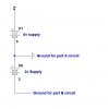
If I had a split power supply (as per screenshot), I could feed the first circuit using the 6v supply and the other via the 8v supply, which would give me the necessary bias.
I have created a sim and it works fine.
However, I havn't a clue how to build the split supply.
I have a DC 9v supply, which I wish to split as 0v - 2v - 8v (the 2v will be used as a ground for part A circuit, whilst true ground will serve as ground for Part B.
I tried resistors but it didnt work well and would prefer a regulated circuit.
Part A draws about 60mA whilst part B draws 10mA


Advice would be appreciated
 

Attachments

  • screenshot.jpg
    screenshot.jpg
    32.8 KB · Views: 191
Last edited:
Not sure if this will help,

I would use a 12v supply and use 2 regulators,

12v in-----8v regulator-----6v regulator.

That way you will have stable outputs, with potential dividers any change in the source supply will result in changes in the output voltages.

With regulators you need to have around 2v more than the required regulated voltage, hence the 12v supply.
 
Hi Rosso,

a voltage divider works precisely if the current flow trough both circuits remains stable.

I suggest to use the full 9V supply for the positive supply and and add a precision reference voltage source for the desired 2V.

Using an LM611 the output voltage is programmable from 1.2 to 6.3V.

Attached is the data sheet of the LM611.

Boncuk
 

Attachments

  • LM611.pdf
    386.9 KB · Views: 293
Not sure if this will help,

I would use a 12v supply and use 2 regulators,

12v in-----8v regulator-----6v regulator.

That way you will have stable outputs, with potential dividers any change in the source supply will result in changes in the output voltages.

With regulators you need to have around 2v more than the required regulated voltage, hence the 12v supply.

But with this suggestion, I would be running one part on 6v and the other part on 8v which would not give me the 2v ground differential (ie I need the ground on one part of the circuit to be 2v higher than the other part of the circuit)
 
Hi Rosso,

a voltage divider works precisely if the current flow trough both circuits remains stable.

I suggest to use the full 9V supply for the positive supply and and add a precision reference voltage source for the desired 2V.

Using an LM611 the output voltage is programmable from 1.2 to 6.3V.

Attached is the data sheet of the LM611.

Boncuk

Do you mean to use the stabilised output from the LM611 as the ground for circuit Part A and the 9v +ve supply as Part A's +ve?

Also, if the 9v is not regulated, and the output from the LM611 is, then wouldnt the 2v differential would vary under load?
 
If the 9V source is not stabilized you won't need a stabilized reference voltage.
 
I'll be able to tell you more if you post a schematic of your project.
 
I'll be able to tell you more if you post a schematic of your project.

Ok, here it is. As you will see the ground on U3 and U4 is higher than that of U1 and U2, which enables me to maintain a bias voltage at 'Solar Out'.

The 2 inputs (V2 & V5) are Current Transformers, and the circuit is designed to switch on a water heater IF solar generated power exceeds what is being consumed.
 

Attachments

  • FullPeak1-split ground.asc
    7 KB · Views: 134
  • screenshot.jpg
    screenshot.jpg
    122.6 KB · Views: 300
Hi Rosso,

this would be my approach.

Use common ground and two different supply voltages.

That's a cheap and reliable method.

Boncuk
 

Attachments

  • SPLIT-POWER.gif
    SPLIT-POWER.gif
    22.9 KB · Views: 389
Last edited:
Status
Not open for further replies.

Latest threads

New Articles From Microcontroller Tips

Back
Top