Continue to Site

Welcome to our site!

Electro Tech is an online community (with over 170,000 members) who enjoy talking about and building electronic circuits, projects and gadgets. To participate you need to register. Registration is free. Click here to register now.

  • Welcome to our site! Electro Tech is an online community (with over 170,000 members) who enjoy talking about and building electronic circuits, projects and gadgets. To participate you need to register. Registration is free. Click here to register now.

SPI configuration

Status
Not open for further replies.

camerart

Well-Known Member
Hi,
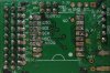
I am using an 18F2420 with an SX1278 radio Chip_module.
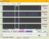
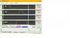
One of my circuits is working but a second circuit is not. I've had it pointed out that the SPI may be too fast and have discovered Define SPICLOCK_STRETCH = X Which I will try today. A second point is that the SPI protocol could be incorrect, but may still work. Does anyone know the Oshonsoft SPI protocol please?

Here is and excerpt from the SX1278 DATA sheet.

"The SPI interface gives access to the configuration register via a synchronous full_duplex protocol corresponding to CPOL=1 and CPHA=0 in Motorola/Freescale nomenclature. Only the slave side is implemented."

Camerart.
 
Last edited:
hi C,
Page #23-11 of this PDF shows the possible 4 clock Modes of the SPI protocol.
Use the Oshonsoft Scope tool to display the Oshonsoft clock and Cs signals, from that you should be able to check which Mode Vlad uses.

The Oshonsoft manual states:
The assumed settings are active-high for Clock line and active-low for ChipSelect line.

This can be changed:
That can be changed by assigning the value 1 to SPICLOCK_INVERT and/or SPICS_INVERT parameters by DEFINE directive.

Manual:
For slower SPI devices, it might be necessary to use longer clock pulses.
The default clock stretch factor (1) can be changed by setting SPICLOCK_STRETCH parameter.

E
https://en.wikipedia.org/wiki/Serial_Peripheral_Interface_Bus
 

Attachments

  • 39699b.pdf
    407.3 KB · Views: 279
Last edited:
Hi Eric,
Thanks for the PDF, but I found it difficult to read as it uses different sets of words for SPI. I have attached one I find easier.

See #2, I tried and failed with Define SPICLOCK_STRETCH.

I have attached images from Oshonsoft showing SPI Prepare-SPICSon-SPICSoff. Note the first write address is 0x31 Or 0x80, and 10110001, then 0x00 so 00000000.

I don't find that the rising falling signals aren't lining up for easy checking.

I'm now going to try SPICLOCK_INVERT.

C
 

Attachments

  • SPI CPHA=0-1 and CPOL=0-1.gif
    SPI CPHA=0-1 and CPOL=0-1.gif
    10.7 KB · Views: 263
  • SPI.jpg
    SPI.jpg
    65.5 KB · Views: 265
  • SPI ZOOM.jpg
    SPI ZOOM.jpg
    64.8 KB · Views: 262
hi C,
The SX expects CPOL=1 and CPHA=0, the Scope Plot is showing CPOL =0 [ Idle LOW going High].??

E
 
hi C,
The SX expects CPOL=1 and CPHA=0, the Scope Plot is showing CPOL =0 [ Idle LOW going High].??

E
Hi Eric,
CPHA is not clear to me.
I see that CPOL (SCK) = 0 (Do they use all these different acronyms, to confuse people like me:confused:)

As mentioned, I've tried Define SPICLOCK_STRETCH up to 20, with no affect.
Also I've now tried SPICLOCK_INVERT also with no change. e,g, the signal runs low till a write, then goes high then low. It may have shifted a little?

EDIT: The problem is with a second circuit board. The first board is working with two SX chip-modules. I will go back to checking the second circuit, which is supposwed to be a neater version than the first one.

C.
 
Last edited:
CPHA is not clear to me.

hi C,
CPHAse=1 means that the Data Bit being transferred is clocked into the buffers when the Clock pulse goes High.

CPHAse=0, means that the Data Bit being transferred is clocked into the buffers when the Clock pulse goes Low.

E
Your SX states: synchronous full_duplex protocol corresponding to
CPOL=1 and CPHA=0

A002.gif
 
Hi Eric,
A quick answer while I study your replies.

If you look at SPI on #4 you will see that all of the resting signals run low until data transfer, when SCK goes high then low. even when SPICLOCK_INVERT is used all of the signals run low until data transfer. On both yours and my images show CPOL=1 as the SCK running high until data transfer.
Either way neither has solved the error on the second circuit of mine.

Do you think that one circuit could work while another circuit won't work, because of SPI timings or wires of different lengths?
C.
 
hi C,
Oshonsoft SPI is not really fast, wire lengths should cause a problem.

You findings ref the SPICLOCK_INVERT puzzles me, it maybe another Oshonsoft bug.?

E
 
hi C,
Oshonsoft SPI is not really fast, wire lengths should cause a problem.

E
Hi Eric,
Assuming that I have made the second circuit correctly?!?! and looking at an Orange module with similar chip-module see attached, where the radio is on the other side of the board to the controller, I'll work on the idea of wire length and make another circuit.
 

Attachments

  • Orange.jpg
    Orange.jpg
    197 KB · Views: 257
hi C,
The CLOCK invert works for me.
E
A003.gif
A004.gif
 

Attachments

  • SPI1.txt
    311 bytes · Views: 242
Hi Eric,
I've tried both Define SPICLOCK_INVERT = 0 and 1 Also Define SPICS_INVERT = 0 and 1

Each time the same, see image. The signals drop at Line 61.

What's going on:banghead:

C.
 

Attachments

  • INVERT.jpg
    INVERT.jpg
    141.9 KB · Views: 264
hi,
Where are you placing the INVERT Defines.??

Define SPI_CS_REG = PORTC
Define SPI_CS_BIT = 2
Define SPI_SCK_REG = PORTC
Define SPI_SCK_BIT = 3
Define SPI_SDI_REG = PORTC
Define SPI_SDI_BIT = 4
Define SPI_SDO_REG = PORTC
Define SPI_SDO_BIT = 5

Define SPICLOCK_INVERT = 1
Define SPICS_INVERT = 1
SPIPrepare

Why are you trying to INVERT CS ?

A008.gif
 
Last edited:
hi,
Where are you placing the INVERT Defines.??

Define SPI_CS_REG = PORTC
Define SPI_CS_BIT = 2
Define SPI_SCK_REG = PORTC
Define SPI_SCK_BIT = 3
Define SPI_SDI_REG = PORTC
Define SPI_SDI_BIT = 4
Define SPI_SDO_REG = PORTC
Define SPI_SDO_BIT = 5

Define SPICLOCK_INVERT = 1
Define SPICS_INVERT = 1
SPIPrepare

Why are you trying to INVERT CS ?

View attachment 103930
Hi Eric,
I'm not particularly trying to invert CS, just trying everything programable, that may get Circuit 2 working.
I was adding the invert lines at the top of the program (OOps) once moved to where you suggest, it now inverts. See image.
I've now tried the speed and invert, and all work in one circuit and not the other, so it must be something else.
I've attached a screen shot from my oscilloscope showing SCK and MOSI, and it shows pretty poor square waves, connected to circuit 1.
Circuit 2 doesn't appear to have the SCK working. I'll investigate!!
Thanks, C.
 

Attachments

  • Inverted.jpg
    Inverted.jpg
    72.8 KB · Views: 254
  • OSC.jpg
    OSC.jpg
    104 KB · Views: 265
hi,
Ref the OSC scope image, are you using a decent scope probe.?
What make of scope is it.?
E
 
hi,
Ref the OSC scope image, are you using a decent scope probe.?
What make of scope is it.?
E
Hi Eric.
There's no name on my probes, and they don't look expensive.
The Scope is a Hameg HM512 with dodgy switches. I would prefer a £1000 upgrade:)
C
 
Hi,
I cleaned up the second circuit tracks, and it slightly changed some of the readouts, so it appears that small changes affect the workings.

I'll go back to plan B and make new circuits with shorter connections.
C.
 
Status
Not open for further replies.

Latest threads

New Articles From Microcontroller Tips

Back
Top