Continue to Site

Welcome to our site!

Electro Tech is an online community (with over 170,000 members) who enjoy talking about and building electronic circuits, projects and gadgets. To participate you need to register. Registration is free. Click here to register now.

  • Welcome to our site! Electro Tech is an online community (with over 170,000 members) who enjoy talking about and building electronic circuits, projects and gadgets. To participate you need to register. Registration is free. Click here to register now.

Spark Gap Transmitters like was on the ship Titanic

Status
Not open for further replies.

gary350

Well-Known Member
I am reading what little information I can find on old spark gap transmitters just wondering how did they work. Did those things have a tuned circuit so it would transmit on a certain frequency? If so then it should have a frequency matching antenna? I read they are CW transmitters?

I would like to see a circuit drawing to get an idea how it worked. I read spark gaps generate 1000s of random frequencies.
 
The spark gap transmitters did have a simple tuned circuit but it still generated a lot of harmonics, so can't be used anymore because of the interference they cause.

They were used only for Morse code transmission as you can't modulate the carrier to transmit audio.

Here'sa discussion.
 
Last edited by a moderator:
I already saw that link. There is no information about antennas in any of that online stuff.

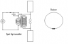
There are some pictures of those old flat wire coil antennas on a flat board the old 1940s radios had those antennas to receive, what about the transmitter did they use the same FLAT coil pancake antenna. The pictures all look like a Tesla Coil power supply circuit without the primary & secondary coils. I figured out from looking at the pictures they are basically an old Model T ignition coil wired so the telegraph key turns the coil on/off.

I am surprised those CW transmitters had a range of 30 miles.

Another interesting thing, when the spark gap gets hot it will not transmit, the spark gaps had to be kept cool with a fan, then rotary sparks gaps were invented. LOL. the rotary spark gap was advancing technology.

Just think about how primitive technology was then, enamel coated copper wire had not been invented yet. Someone learned how to make carbon rods to make better spark gaps. It is hard for me to imagine how primitive ALL technology was in those days. Every thing was made with brass and cast iron, very primitive steel had just been invented.

All technology is limited by other technology they all need to advance at the same rate.
 
Some of the early antennas were wires connected to balloons. As the wind changed the tuning on the antenna changed and adjustment was needed.

Years ago, my transmitter burned off the points and I needed to screw the points closer together often.
Mom read a book on Marconi to me. I set out to do the experiments. First transmitter was two frying pans with sparks between them. Much better with tuning coils made on toilet paper roles.

upload_2017-10-7_5-46-57.png


I never used the spark receiver because I knew it was not good. I did use a crystal receiver.
 

Attachments

  • upload_2017-10-7_5-48-10.png
    upload_2017-10-7_5-48-10.png
    6.3 KB · Views: 136
Look up leydan jar transmitter, they were a very early marconi oscillator transmitter, allthough marconi oscillator is a correct term these were before marconi.
 
The brilliance of those pioneers is to be admired. The first microphones used a flame to change resistance!
 
I dont know if thats how it was done originally but you can use a flame as the rectifier diode in an Am receiver.
 
Status
Not open for further replies.

New Articles From Microcontroller Tips

Back
Top