Continue to Site

Welcome to our site!

Electro Tech is an online community (with over 170,000 members) who enjoy talking about and building electronic circuits, projects and gadgets. To participate you need to register. Registration is free. Click here to register now.

  • Welcome to our site! Electro Tech is an online community (with over 170,000 members) who enjoy talking about and building electronic circuits, projects and gadgets. To participate you need to register. Registration is free. Click here to register now.

Sound system. no more power

Status
Not open for further replies.

jerome357

New Member
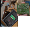
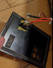
Hi all. I have a sound tower that doesn't turn on at all.
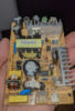
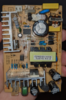
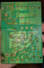
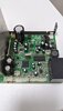
there is no more power. No on/off lights are on when I turn the power button on. I disassembled the electronic card, and visually, it looks in good condition, does not feel it burn, and the fuse of the card also looks good. I changed the male plug, (I plugged the device in different places, but it doesn't change anything).
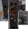
question: would there be another fuse hiding this in the tower?
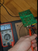
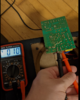
The difficulty is that I don't have a tester.
 

Attachments

  • PXL_20210605_091215506.jpg
    PXL_20210605_091215506.jpg
    1.5 MB · Views: 293
  • PXL_20210623_023742234.jpg
    PXL_20210623_023742234.jpg
    1.6 MB · Views: 295
I believe Nigel meant "Where are [the photos of] the power supply"?

You need to provide photos of all circuit boards and connections, from both top and bottom views, so the electrical connections can be traced all the way from the power input and through the circuitry, to have any chance of someone being able to remotely diagnose such a fault.
 
The pictures aren't any use - it's like you were complaining your car won't start, and posted a picture of the back type for diagnosis.
Alright, I took photos and traced the connection. (I'm not a graphic designer :) ). is that ok ?
 

Attachments

  • Untitled.png
    Untitled.png
    1 MB · Views: 273
  • v2 Untitled.png
    v2 Untitled.png
    842.1 KB · Views: 273
  • v3 Untitled.png
    v3 Untitled.png
    1.7 MB · Views: 268
the power supply seems to be on the board, and i think there's a power transformer that connects to the large two-pin connector in the upper right corner of the board....
 
the power supply seems to be on the board, and i think there's a power transformer that connects to the large two-pin connector in the upper right corner of the board....

Which is the main component of the PSU :D

We need to know what's in there so we can suggest what to test. 'If' it's a 50/60Hz mains transformer, then there's a decent possibility that it's internal heat fuse has died - but if it's a switch mode PSU in there, it will read much like a blown heat fuse if it's good.

It looks like there's only a single rectifier on the board, as well as a soldered in fuse - half wave rectification would be no good, so it could be DC coming up, and the rectifier is a polarity protection diode?.

But basically we're all blindly guessing, because the bits we need to see are in the bottom.
alright, sorry. i didn't know the Power supply was hidden in the bottom. I found it. I check visually the fuse and it looks fine...
 

Attachments

  • alim v1Capture.PNG
    alim v1Capture.PNG
    931.9 KB · Views: 249
  • alim v2Capture.PNG
    alim v2Capture.PNG
    880.2 KB · Views: 254
  • Alim v3Capture.PNG
    Alim v3Capture.PNG
    862.1 KB · Views: 260
You need a multimeter to check the power switch and measure the voltage out from the power supply board.

From the photos, the two connectors near the big yellow capacitor are power in from the mains connector, and the wires to the power switch.

The two pin connector at the opposite end of the PSU is DC out to the rest of the amplifier.

The first thing to do is test the switch, from the connector that should go to the board - it could be as simple as a failed power switch.


When you get a meter, do not do any tests with power connected without explicit instructions, as there are lethal voltages on the PSU if you touch the wrong part!
 
I'll add to that, be very careful when handling the power supply even when it has been unplugged for a while - avoid touching the connections on the rear until you can check with a meter that there is no stored voltage.
 
You need a multimeter to check the power switch and measure the voltage out from the power supply board.

From the photos, the two connectors near the big yellow capacitor are power in from the mains connector, and the wires to the power switch.

The two pin connector at the opposite end of the PSU is DC out to the rest of the amplifier.

The first thing to do is test the switch, from the connector that should go to the board - it could be as simple as a failed power switch.


When you get a meter, do not do any tests with power connected without explicit instructions, as there are lethal voltages on the PSU if you touch the wrong part!
Hi,
Something I don't understand, when I put the multimeter on the pin directly, I found 230V, but when I test on the welds, then there is nothing. 0V.
I tested the main switch, and it seems to work.
What should i do now ?

Thx
 

Attachments

  • v4Capture.PNG
    v4Capture.PNG
    996 KB · Views: 248
  • v5Capture.PNG
    v5Capture.PNG
    785.2 KB · Views: 243
  • v6Capture.PNG
    v6Capture.PNG
    773.3 KB · Views: 247
What is the next step, please ?
As you said, the PCB may be varnished, so how could I test the component, the capacitor etc...
 
What is the next step, please ?
As you said, the PCB may be varnished, so how could I test the component, the capacitor etc...

Have you ever noticed the points on the end of your meter probes? - have you ever thought why they might be pointed?.

The points will simply push through the varnish.
 
Status
Not open for further replies.

Latest threads

New Articles From Microcontroller Tips

Back
Top