Continue to Site

Welcome to our site!

Electro Tech is an online community (with over 170,000 members) who enjoy talking about and building electronic circuits, projects and gadgets. To participate you need to register. Registration is free. Click here to register now.

  • Welcome to our site! Electro Tech is an online community (with over 170,000 members) who enjoy talking about and building electronic circuits, projects and gadgets. To participate you need to register. Registration is free. Click here to register now.

Sound detection circuit

Status
Not open for further replies.

Retard

New Member
Hey guys someone recommended this site to me and said you might be able to help with this problem I'm trying to tackle.
I've drawn a circuit and I don't know if it is right or not, any help would be greatly appreciated.


Situation:

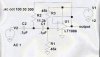
A circuit that will switch on a tape recorder when the input sound level is above a certain threshold and record for a preset amount of time (adjustable in the range 1 to 10 minutes). Include a filter to stop the recorder being triggered by 100 Hz wind noise. And you use batteries for this.

Thanks in advance for any feedback on :)

P.S sorry the op-amp is meant to be acting as an active high-pass filter there and I would just need to add a capacitor before R1 to make it a filter right? And the Microphone symbol has been cut slightly so it is the open circle there on the left.
 

Attachments

  • 60351.jpg
    60351.jpg
    13.2 KB · Views: 1,400
Hi Retard,
The air turbulence caused by wind around a microphone is mainly lower frequencies, but many more than only 100Hz, all the way up to 1kHz or higher. Maybe your microphone is cheap with a bad resonance at 100Hz but wind noise will certainly be picked-up by it at many other frequencies in the voice and music band. Foam or hairy windscreens are used by audio professionals and work well in light winds.

A single capacitor makes a lousy filter anyway. If it was designed to reduce 200Hz to 0.7, then 100Hz would be reduced to 0.5. If it was designed to reduce 1kHz to 0.7 so there isn't much bass, then 100Hz would be reduced to 0.1, still plenty of level to trigger a timer if a strong wind gust occurs.

You have drawn an opamp circuit that needs positive and negative voltages for its power supplies. With a single power supply voltage it will need biasing to work properly. Also, its output will need a coupling capacitor to the pull-up resistor at the trigger input of a timer.
 
Well the specifics about the wind aren't required.
It's a situation that one of my friends gave to me from his lectures.
I'm just starting out with electronics.
Anyway you would assume that the wind noise is only 100 Hz.
The only thing to be considered is the roll-off of the high-pass filter that is trying to leave out the 100 Hz.
So you're also saying that I should have a battery powering the op-amp as well?
 
You cannot assume that wind noise will occur only at 100Hz, it is wide-band noise and if you try to filter it out, you will also filter out voice and music frequencies.

Of course the opamp can be powered by a battery, it needs to be powered by something. Maybe a wind powered generator? :lol:
 
haha ok stupid question really.
But yeah I'm saying that I'm just trying to design the circuit that was given in my friend's notes.
It says assume that the wind noise is 100 Hz and below and filter out frequencies in that range.
So the detection circuit will only start recording above 100 Hz.
 
hey guys I read somewhere that you can't connect an analog signal straight to the timer to trigger it.
Why is this? I thought that the timer 555 had built-in comparators?
 
Hi Retard,
The detection circuit will be triggered by frequencies only above 100Hz only if you use a lowpass filter much more complicated than the simple one-capacitor one you were going to use, because its cutoff slope is very gradual.

The 555 timer doesn't have a sensitive trigger input. It needs to be fed from the output of a preamp for the analog signal. The preamp can be the opamp in your circuit but it must be powered from the same supply voltage as the 555.

An ordinary 555 draws a huge current surge from the power supply each time its output switches which can upset the preamp on the same supply. Therefore I recommend using the Cmos version such as an LMC555.

As Russ explained, you will have trouble getting a timing period as long as 10 minutes from a 555 timer. It will need very high values for its timing resistor and capacitor. Adjustable very high-value resistors aren't available and high-value capacitors have a leakage current too high to use with a high-value resistor. If you use a 1Meg potentiometer, then you need 660 1uF low-leakage non-electrolytic capacitors. That is why he recommended using a timer with a digital divider in it.
 
Thihs is a 100 Hz high pass filter. You can change the frequency by changing the RC in an inverse ratio. That is, 1/2 the capacitance will double the frequency.
 

Attachments

  • hipass_102.jpg
    hipass_102.jpg
    33 KB · Views: 994
Russ's highpass filter will have an output like this:
1000Hz = 1.0
100Hz = 0.7
50Hz = 0.25
25Hz = 0.0625.
Even though it uses many more parts than a simple single highpass filter, it still has a fairly gradual cutoff slope. :lol:
 
Status
Not open for further replies.

Latest threads

New Articles From Microcontroller Tips

Back
Top