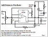
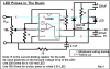
The parts are much too far apart. Why isn't the LM386 IC on the Veroboard with the rest of the parts? It will probably oscillate at a very high frequency unless all grounded parts are connected directly to the ground pin 4 of it.
Also the 470uF power supply filter cap needs to be connected directly to the supply pin 6. The 0.05uF cap needs to be connected directly to its output pin 5.
When I say "directly", I mean without the inductance and resistance of wire longer than about 1cm.
I design my Veroboard layouts with the strips horizontal like on the schematic. Then parts mount beside the IC on its strips with extremely short wiring and tight spacing.
Like most ICs, the LM386 has a bandwidth of at least 300kHz so the pcb layout and wiring must be treated the same as an RF circuit.
You should cut the Veroboard strips with a drill-bit or proper tool so that there isn't any extra length causing capacitive-coupling to adjacent strips.
When you wire LEDs in parallel, probably only one will light brightly and the other will be dim. LEDs all have a slightly different voltage and the one with the lowest voltage requirement will be bright, and the other won't get its required voltage and will be dim.
If you are lucky and their voltage requirements are the same, then they will share the available current and therefore each will not be as bright as just one.