Continue to Site

Welcome to our site!

Electro Tech is an online community (with over 170,000 members) who enjoy talking about and building electronic circuits, projects and gadgets. To participate you need to register. Registration is free. Click here to register now.

  • Welcome to our site! Electro Tech is an online community (with over 170,000 members) who enjoy talking about and building electronic circuits, projects and gadgets. To participate you need to register. Registration is free. Click here to register now.

Someone please explain how this BMS board is supposed to work?

Status
Not open for further replies.

nzoomed

Member
I was told to get one of these to charge a bank of 4x 21700 lithium batteries.
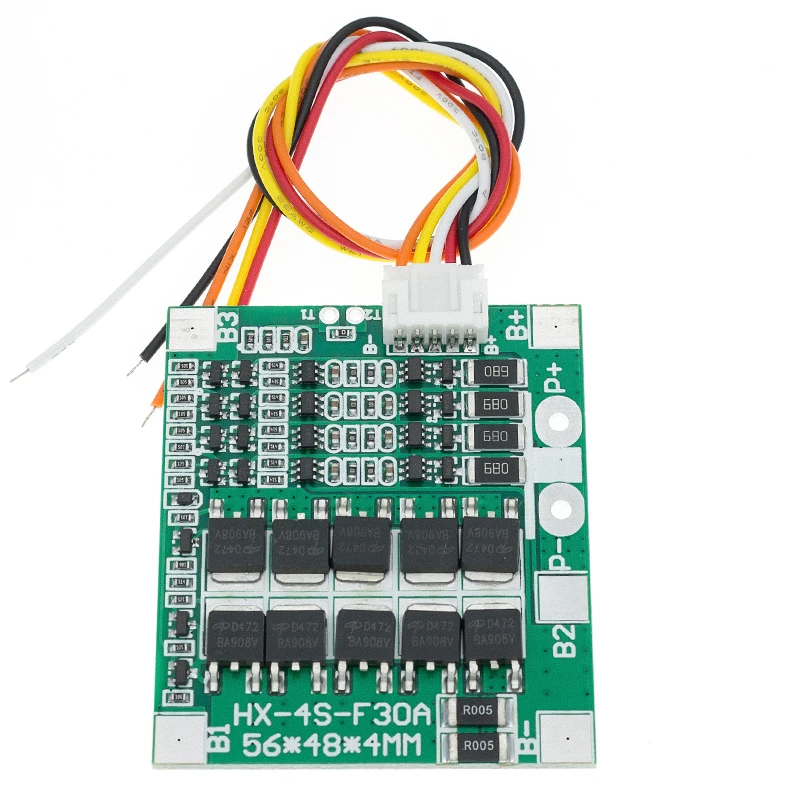
Its model no is cf-4s30a
Now my first concern is that it says its only 14.8V, but my batteries measure 15.6V across all 4 when fully charged.
14.8V isint even enough voltage to charge the bank of batteries, so is it safe to use a higher input voltage?
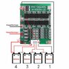
Ive started wiring it up to the battery pack when I noticed that the positive and negative charge/discharge terminals directly connect to B+ and B- respectively on the board itself. In other words, I dont see how this is supposed to offer any charge or discharge protection, as there is nothing between the bank of batteries to control current going in or out across the batteries.

It appears to be just a battery balancer and not a charger itself, i doubt it even is designed to protect the batteries by the looks of it.
I want to use a 20W, 12V solar panel to provide its charging power, what kind of solar controllers are available for charging a lithium bank of 4 batteries? I cant seem to find anything suitable.
 
It's a battery protection and cell balance board. It should disconnect the battery from the external wiring if any cell gets over-discharged or over-voltage. The balance network should equalise voltage and allow charging to continue if one cell reaches maximum voltage before the others.

In summary, it should prevent the cells being wrecked by over-discharge or exploding due to overcharge.

It is not a charger or charge control board, that is a totally separate function. The charge controller needs to regulate the voltage to the battery pack to 4.20V per cell, plus have a current limit so the pack does not get excess current when the cell voltage is low.

See the circuit below as an example.

I've used similar battery protection/balance boards, they seem OK. Just avoid ones that do not include both functions.

ps. Lithium packs are commonly rated at mid-charge voltage, like other rechargeables - based on 3.6 - 3.7V per cell for lithium types. That's where the 14.8V comes from.

The power switch FETs appear to be between B- and P- on your board.

Battery_with_board.jpg


This is a simple charger circuit I designed for use with a battery pack built like that; it's made to also bypass the battery pack and run the load directly when external power is available, so the charging is not affected be load.

Schematic_Charger_2022-05-19.png
 
Last edited:
It's a battery protection and cell balance board. It should disconnect the battery from the external wiring if any cell gets over-discharged or over-voltage. The balance network should equalise voltage and allow charging to continue if one cell reaches maximum voltage before the others.

In summary, it should prevent the cells being wrecked by over-discharge or exploding due to overcharge.

It is not a charger or charge control board, that is a totally separate function. The charge controller needs to regulate the voltage to the battery pack to 4.20V per cell, plus have a current limit so the pack does not get excess current when the cell voltage is low.

See the circuit below as an example.

I've used similar battery protection/balance boards, they seem OK. Just avoid ones that do not include both functions.

ps. Lithium packs are commonly rated at mid-charge voltage, like other rechargeables - based on 3.6 - 3.7V per cell for lithium types. That's where the 14.8V comes from.

The power switch FETs appear to be between B- and P- on your board.


This is a simple charger circuit I designed for use with a battery pack built like that; it's made to also bypass the battery pack and run the load directly when external power is available, so the charging is not affected be load.
Thanks, that was what I was assuming was the case, i was just confused how it was all supposed to work, as when i was checking my connections my multimeter indicated continuity both directions with leads reversed or not which made me think there cant have been any diodes or other electronics in the way. Will the FETs behave like this normally with a multimeter?
See the attached photo, the arrows ive drawn show where i was making connections with the probes on my multimeter.
 

Attachments

  • 3b350a3564336cae5e4600d25cbc9f2f91bc2396_original.jpeg
    3b350a3564336cae5e4600d25cbc9f2f91bc2396_original.jpeg
    177.5 KB · Views: 201
Once it's connected to power and enabled itself, the power switch FETs will be on, unless there is a fault condition that causes it to isolate the battery.

On the one I have to hand, there is less than 20 milliohms resistance through the FETs; it's not obvious on a normal multimeter.

I'd expect it to show open circuit with no power connected at all?

I don't have a spare of that type about, but I have a five cell 50 amp one; that does show open circuit between the battery negative and out negative (several megohms, anyway).
OK, perhaps my meter is not very sensitive? I had it set to continuity and it was beeping off like it does when its presumably zero ohms or thereabouts. Im not sure that resistance trips it off, might be still low enough for it to trigger it?
 
Im not sure that resistance trips it off, might be still low enough for it to trigger it?
The multimeter continuity "beep" generally operates up to a few ohms resistance, while the FET ON resistance is a tiny fraction of an ohm.

The meter would see it as a continuous circuit; its less than the resistance of just the meter leads themselves.
 
The multimeter continuity "beep" generally operates up to a few ohms resistance, while the FET ON resistance is a tiny fraction of an ohm.

The meter would see it as a continuous circuit; its less than the resistance of just the meter leads themselves.
OK, got it. So basically the gates are open on these FETs and giving me a reading.
 
The NEGATIVE IN to NEGATIVE OUT should measure open-circuit when board has no supply

Positive is common (even if the board has maybe two holes, they are on the same copper trace)


When you connect the bms to battery (B-, B+) and the small wires are also connected to intermediate cell connections, if the voltage of each cell is in normal range, the BMS will allow current pass betw B- and whatever is other negative simbol on the board (possible P-, L-)

The NEGATIVE is disconnected when a cell is out of range.
 
Status
Not open for further replies.

Latest threads

New Articles From Microcontroller Tips

Back
Top