Continue to Site

Welcome to our site!

Electro Tech is an online community (with over 170,000 members) who enjoy talking about and building electronic circuits, projects and gadgets. To participate you need to register. Registration is free. Click here to register now.

  • Welcome to our site! Electro Tech is an online community (with over 170,000 members) who enjoy talking about and building electronic circuits, projects and gadgets. To participate you need to register. Registration is free. Click here to register now.

Some questions on 3s 18650 battery packs

Status
Not open for further replies.

Vizier87

Active Member
Hi guys, sorry if this has been extensively discussed. I've gone through posts in ETO on similar issues but I still had a few concerns.

Based on a week of Googling and watching videos on managing 18650 Li-Ion batteries, I came to a few conclusions:


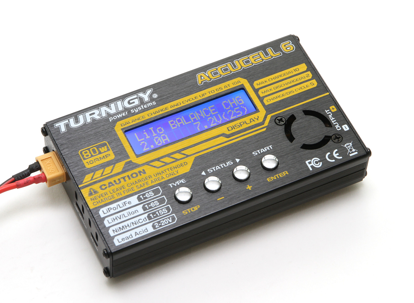
If we want to do away with the bulky balance chargers, then:
1. We need Battery management systems (BMS) like these for mitigating overcharge, over-discharge, and short-circuits.
2. BMS modules does NOT perform balance charging.
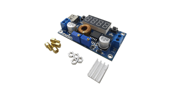
3. If you want to recharge a, say, 3S battery pack made of the 18650 cells, you need a separate constant current, constant voltage module.
4. If you want to BALANCE charge, you need to install separate balancing module like these?

Did I understand this correctly?

Any corrections to my understanding is very much welcome.

Thanks!
Vizier87
 
Protection board including balance are readily available, you just have to be sure of what you are buying as the sellers often don't have a clue!

Combining different protection and balance modules is not a good idea, as there is no guarantee the balance will work below the cutoff threshold of the protection board, as those disconnect the power input as soon as any cell reaches a threshold.
I have tried it and it's a "never again" situation, as it caused serious problems with the gear I used the battery packs in.

The photo below is the type of thing I use now, on a three cell (two parallel) pack, as it happens. I use that with a built up constant voltage + current limit charge circuit.
Protection boards like those are easy to find on ebay, eg. these are similar, just different max current ratings:


For things that have removable packs, I prefer to use a basic protection board plus a proper balance charger that connects direct to every cell; I have a Turnigy one made for such as RC flight batteries, which is fully programmable for number of cells, battery type and current etc. and that works very well.

Or just loose 18650 cells & use multi cell or stackable holders, with a separate dedicated 18650 charger.

I also use power tool batteries for some things, with 3D printed "sockets" to mount the to whatever they are powering.. The Aldi 20V & 40V batteries are cheaper than buying good quality loose cells; I put the connector design for those on Thingiverse. The box in the photo is a regulated 15-0-15 supply for testing analog gear.

And ps. Do not ever try to recharge series lithium cells without a balance system of some sort in place - that's what causes burst cells and fires...

Battery_3S2P_800.jpg Battery_Adapter_800.jpg
 
Protection board including balance are readily available, you just have to be sure of what you are buying as the sellers often don't have a clue!

Combining different protection and balance modules is not a good idea, as there is no guarantee the balance will work below the cutoff threshold of the protection board, as those disconnect the power input as soon as any cell reaches a threshold.
I have tried it and it's a "never again" situation, as it caused serious problems with the gear I used the battery packs in.

The photo below is the type of thing I use now, on a three cell (two parallel) pack, as it happens. I use that with a built up constant voltage + current limit charge circuit.
Protection boards like those are easy to find on ebay, eg. these are similar, just different max current ratings:


For things that have removable packs, I prefer to use a basic protection board plus a proper balance charger that connects direct to every cell; I have a Turnigy one made for such as RC flight batteries, which is fully programmable for number of cells, battery type and current etc. and that works very well.

Or just loose 18650 cells & use multi cell or stackable holders, with a separate dedicated 18650 charger.

I also use power tool batteries for some things, with 3D printed "sockets" to mount the to whatever they are powering.. The Aldi 20V & 40V batteries are cheaper than buying good quality loose cells; I put the connector design for those on Thingiverse. The box in the photo is a regulated 15-0-15 supply for testing analog gear.

And ps. Do not ever try to recharge series lithium cells without a balance system of some sort in place - that's what causes burst cells and fires...

View attachment 134433 View attachment 134434

Hi Mr Jenkins,

Thanks for the input. Yeah, the BMS module you mentioned is pretty similar to the one I have in mind.

The Turnigy device like the one you use, is also similar to mine (LiPro IMAX B6).

So if we have the BMS/balancing module connected to each of the batteries in series, we STILL have to use the balance charger like your Turnigy, right?

Edit: I am slightly puzzled by the design of these balance chargers, especially (for the case of 3 cells in series) the seemingly redundant bifurcation of the common +ve and -terminals. These terminals are also part of the balancing for say, Battery 1 and Battery 3. So why not just make the balancing with only four terminals?

Cheers!
 
Last edited:
So if we have the BMS/balancing module connected to each of the batteries in series, we STILL have to use the balance charger like your Turnigy, right?
No; if it's a properly made combined protection + balance module, you just need a (current limited) constant voltage supply.
That allows you to safely charge batteries that do not have built-in balance systems.

dit: I am slightly puzzled by the design of these balance chargers, especially (for the case of 3 cells in series) the seemingly redundant bifurcation of the common +ve and -terminals. These terminals are also part of the balancing for say, Battery 1 and Battery 3. So why not just make the balancing with only four terminals?
The protection part is in series with the external connections, to allow the battery to be isolated from the external wiring in case of over-charging or over-discharge.

If you look at my photo, the red and black are the external battery terminals, for both the equipment load and charging.
The brown and white are the battery main terminals to the protection board & grey wires the "taps" between cells.

Or do you mean the external charger such as the Turnigy?
With those, it's likely done to avoid voltage drops if trying to measure by the same wires as providing the high current charge, as the balance circuits are working to millivolts and a charger such as those could be on long connections to a battery fitted in a model or drone etc., with significant losses in the power connections.
 
This is the circuit I built to charge that three cell pack with the protection/balance board on top. It runs from a regulated supply at around 14V and has diodes around it to allow the load to run from that input supply while the battery is charging; a kind of UPS for the electronics in a robot project.
(In that, it feeds some things that use an unregulated supply and a switch-mode 5V 10A regulator module).

R1 sets the current limit; when there is around a 0.6 - 0.7V drop across that, the transistors start to turn on and pull down the voltage on the regulator ADJ terminal to reduce the output current. The capacitors are whatever is needed for the regulator to be stable & the actual unit has some 0.1UF ceramics as well.

The exact transistor types are not critical, those are just some I picked for the drawing.

For other cell counts, change R6 and VR1 to get an adjustment range close around the required battery voltage (plus diode drop, if used) as you can, then set for the exact voltage using the preset.

As a charger only, you could leave out the diodes, or just leave out D2 and connect the battery to the load output, adjusting the voltage to compensate for the drop across the output diode. That would avoid any slow discharge via current back through the charger.

The battery pack in use must have a combined balance and protection board fitted, otherwise things may get nasty...

Schematic_Charger_2021-11-12.png
 
Or do you mean the external charger such as the Turnigy?
With those, it's likely done to avoid voltage drops if trying to measure by the same wires as providing the high current charge, as the balance circuits are working to millivolts and a charger such as those could be on long connections to a battery fitted in a model or drone etc., with significant losses in the power connections.
Yeah, I meant those.

I see, that makes sense. Now I can see why many battery packs have so many terminals.

So basically, BMS boards allow balancing as well, and we can charge it with a constant current and voltage source for safe and long-term use.

I just wonder why the constant voltage/current board is not integrated as well into the BMS design though? I've seen the buck converters out there which they used for that purpose and they don't look too bulky for integration... like this one:

Anyhow, thanks a lot for the circuit too.
 
Status
Not open for further replies.

Latest threads

New Articles From Microcontroller Tips

Back
Top