Continue to Site

Welcome to our site!

Electro Tech is an online community (with over 170,000 members) who enjoy talking about and building electronic circuits, projects and gadgets. To participate you need to register. Registration is free. Click here to register now.

  • Welcome to our site! Electro Tech is an online community (with over 170,000 members) who enjoy talking about and building electronic circuits, projects and gadgets. To participate you need to register. Registration is free. Click here to register now.

Some help with mic preamp to vu meter

Status
Not open for further replies.
load

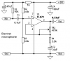
I dont have anything connected to the load.. just yet. If i get it to work i plan to connect it a circuit which has an tl 071 microphone op amp with an lf 351 precision half wave rectifier. Is there another rectifier circuit I can build that doesnt use negative voltage? or what can I do any suggestions?
 
Before you had -1V and now you have only -0.16V. I don't know why the output voltage is dropping.
Try another 555 IC and new 9V battery.
 
replaced chip..

I replaced the 555 timer and now im getting negative one volts, the power is coming from a dc power supply not a nine volt battery but I dont suspect this would be the cause..
 
Is there another rectifier circuit I can build that doesnt use negative voltage? or what can I do any suggestions?
My MC33172 circuit is a mic preamp (like the TL071 mic preamp) plus a precision half-wave rectifier circuit but not needing a negative supply voltage. That is all you need.
 
mc33172

Hi im not getting any audio like wave forms at output or pin1 and or output or pin 7. How can I check to see if I didnt blow my chip or what would you recommend to debug this?
 
The DC output at pin 1 should be half of the supply voltage. The first opamp has an AC voltage gain of 101 so there should be plenty of signal at pin 1.

The DC output voltage at pin 7 should be about +50mV without a signal and follow the peak swings of the signal. The second opamp has an AC voltage gain of 1.

The DC output of the circuit should be the peak voltage of the signal with a fast rise and a slow decay.

How are you measuring the output voltages of the opamps and of the circuit?
 
circuit measure

i am using an oscilloscope mostly and a multimeter for the non signal stuff just to check to see if im getting power.. I will check these parameters and see if im getting what i need to be.. Thank you
 
Measurments

vcc =5v
pin 1 = 4.34v dc
pin 7 = 0.10v dc no input or mic.

----
vcc =9v
pin 1= 8.30v dc

any suggestions?


=====================U.$.==========================
The DC output at pin 1 should be half of the supply voltage. The first opamp has an AC voltage gain of 101 so there should be plenty of signal at pin 1.
The DC output voltage at pin 7 should be about +50mV without a signal and follow the peak swings of the signal. The second opamp has an AC voltage gain of 1.
The DC output of the circuit should be the peak voltage of the signal with a fast rise and a slow decay.
How are you measuring the output voltages of the opamps and of the circuit? _________________
Uncle $crooge
 
simple TL071 Circuit with an lm3915.

1)I wanted to know how to connect a tl071 mic amp like the one provided in this thread to an lm3915. Is a rectifier circuit need? That is done.

2) The main problem lies with pins 2 thru 9.

I have;
v- pin2 to ground
v+ pin3 to vcc
divider low end pin 4 to ground
signal input pin 5 from mic output.
diver high end pin 6 tied to pin pin7
ref output pin 7 r1=1k, r2=2.7k, to ground
ref adjust pin8 tied between r1 and r2 above
mode select pin 9 to vcc for led selection

anyone see any fundamental flaws here or any suggestions?

No capacitor to leds.
 
Last edited:
1)I wanted to know how to connect a tl071 mic amp like the one provided in this thread to an lm3915. Is a rectifier circuit need? That is done.
It works a lot better with a peak detector from the preamp to the LM3915. But you did not post your latest schematic so I don't see your rectifier circuit.

The main problem lies with pins 2 thru 9.
The datasheet and my circuit shows what to do with them.

I have:
signal input pin 5 from mic output.
No.
The signal level from the mic is much too low. It needs a preamp to increase it to a few volts. Pin 5 needs a resistor to ground so that it is 0V without a signal that is fed through a coupling capacitor.

divider high end pin 6 tied to pin pin7
ref output pin 7 r1=1k, r2=2.7k, to ground
ref adjust pin8 tied between r1 and r2 above
Then all the LEDs will try to light when the input is +4.625V which is not possible when the supply is only 5V. The max reference voltage is +3.5V when the supply is only +5V. Your reference voltage is set wrong.
The current in the LEDs will try to be 12mA each.

No capacitor to leds.
Without a schematic then I do not know what you are talking about.
 
Last edited:
schematic

Below is what i have built on breadboard working.
I added a 100k resistor so its 0volts with no signal, is that too much resistance? Also either all lights turn on or they all turn off when mic is getting signal.
the input to pin five is the output from half wave peak detector.
 

Attachments

  • nov21.JPG
    nov21.JPG
    27 KB · Views: 416
  • Electret mic preamp.PNG
    Electret mic preamp.PNG
    5.1 KB · Views: 923
  • schem1.JPG
    schem1.JPG
    85 KB · Views: 497
I added a 100k resistor so its 0volts with no signal, is that too much resistance?
Where is the 100k resistor?

Also either all lights turn on or they all turn off when mic is getting signal.
Then something is wrong.
All LEDs should be turned off without a signal.
The first LED should turn on with a low signal then more LEDs should also turn on as the signal gets louder. All LEDs should turn on when the signal is 30dB louder than when the first LED lights.

Connect pin 4 of the LM3915 to 0V.

You show a 1M resistor at the output of the peak detector which is correct. But you also show a 10k resistor at the pin 5 input of the LM3915 to ground that should be removed because the 1M resistor is there.
 
r1 = 100k resistor sorry

with pin 4 to ground I have only the last two leds flickering and the other eight are on. I removed the r1 = 100k at pin five becasue of the 1M resistor from the ouput of the half wave peak detector. How do I get the flickering to start from the least significant led(say led 1 or 2) instead of almost the most significant (led 8)?
The led light intensity is nice and bright...
 
The half-wave peak detector has too much offset voltage.
Use the half-wave peak detector circuit that I use using an MC33171 single or MC33172 dual opamp and a transistor.
 
Hi Carbajal739, I was reviewing what you are trying to do and it seems interesting. I am doing similar of what you are doing and I look forward to help you too. I am studying at MIT and Im specializing my studies primarly in audio, so I think that we can work together. It would be so great if you can give me more details about your project. I really appreciate it, see ya buddy.
 
offset voltage

Scrooge, Its not that I dont like your mc33172 circuit. I built it and it got messy on me and I have no idea weather my chips are dual or single.

Is there any way to lower the offest voltage from what i have? Heres what I figured out puting voltages instead of the signal from the mic amp.

LED1 0.2V
LED2 0.4V
LED3 measurement not taken
LED4 0.6V
LED5 0.9V
LED6 1.1V
LED7 1.4
LED8 2V
LED9 3V
LED10 4V

I tried a 10m and 3.3m resistor before the input to pin five but nothing really happend. Is there a way to make it work or do I need some fundamental or technical know how to do it?
 
Last edited:
reply

Audionerdieux,
Hi thanks for jumping on board this thread. Anything you would like to know I will share the info. Audio is an intresting thing especially the logarithmic domain.
 
Scrooge, Its not that I dont like your mc33172 circuit. I built it and it got messy on me and I have no idea weather my chips are dual or single.
Look at the datasheet:
The MC33171 is a single opamp.
The MC33172 is a dual opamp.

Is there any way to lower the offest voltage from what i have? Heres what I figured out puting voltages instead of the signal from the mic amp.

LED1 0.2V
LED2 0.4V
LED3 measurement not taken
LED4 0.6V
LED5 0.9V
LED6 1.1V
LED7 1.4
LED8 2V
LED9 3V
LED10 4V
It looks like the base-emitter voltage of the transistor does not match the forward voltage of the diode when the current in the diode is almost nothing.
 
audio decibel meter lm386

Hi I wanted to create an audio decibel meter using an lm386 with an lm3915.

I can connect a speaker to the output of the lm386 and hear the input at the output with a speaker. I need to know what i need to merge the two IC's so that they can work together. I have a decibel meter for calibration but at this point it is useless. I connected both grounds together as to make a common ground. Input to Pin 5 on the lm3915 is the output of the lm386 but I'm really not getting anything..Any ideas or help would be greatly appreciated..Thanks..

Hi i'm new on this forum to, and i whant to create the same project but onlie whit LM 386 **broken link removed** . I must display the sound intensity from input(from microphone) in dB. I must use ATmega64 which is included on a test board (CEREBOT). I must read the signal from preamp output and display'it in dB, of course using ADC (I dont know how i must programm the ATmega64 to do this ). Can somebody help me. My preamp is one board and the CEREBOT is another one. I must use the Code Vision AVR HP InfoTech, Development Tools for Microcontrollers, C Compilers, In-System Programmers programming environment. My project is simplyfied and attached below.

10q
 

Attachments

  • Preamplif microfon.gif
    Preamplif microfon.gif
    25.3 KB · Views: 730
Status
Not open for further replies.

Latest threads

New Articles From Microcontroller Tips

Back
Top