carbajal739
New Member
Sound level meter in dB
I need to take sound from the environment and display that sound intensity in terms of decibels from 0 to 120 db on an lcd screen that is controlled from the microcontroller.. 50 to 100 db would work also. And yes Sir my LEDS are dim..should I change my lm386 to an lm741? I can do that fairly easily..
The problem I have with my so called working circuit is interfacing to port A into the microcontroller..I do not have to worry about how the programming and all works for the microcontroller becasue that part is done. All I have to do is find a way to send eight bits of data to an atmega 32. That data should be read by the atmea32 to represent the environment sound. Here are three things I could do, with some help of coarse..
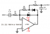
1: lm386 or opamp(lm741?) to an adc 0803(analog to digital converter) sending voltage values in binary (8 bits) form to the atmega 32, then its just information manipulation..using the db formula db=20log(v1/vref), where v1 is the voltage im getting at the output of my opamp...
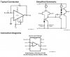
2: lm386 or an opamp to the lm3915 and interface it with an atmega 32 microcontroller...which isnt working becasue Im guessing the lm3915 is logic low meaning it gives ground to turn LEDs on not a voltage which would be great..and also it is probably too fast for an o-scope and the atmega 32 microcontroller...(no cleary defined 1 and 0 but some sawtooth looking graph in o-scope)
3. lm386 or opamp(lm741?) directly to the microcontroller which has a built in a/d converter and then its just code from there.
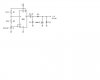
Also im thinking of doing a cascaded lowpass and highpass filter for a bandpass filter with corner frequencies of 20hz to 20khz which is the human threshold of the human ear..
carbajal739
=============================================
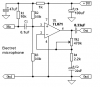
audioguru: Why are you using an LM386 power amplifier instead of an opamp?
The display will look like a dim blur if you do not use one of the peak detector circuits shown in the datasheet for the LM3915.
Your micro-controller does not have an input. What do you want it to do?
I need to take sound from the environment and display that sound intensity in terms of decibels from 0 to 120 db on an lcd screen that is controlled from the microcontroller.. 50 to 100 db would work also. And yes Sir my LEDS are dim..should I change my lm386 to an lm741? I can do that fairly easily..
The problem I have with my so called working circuit is interfacing to port A into the microcontroller..I do not have to worry about how the programming and all works for the microcontroller becasue that part is done. All I have to do is find a way to send eight bits of data to an atmega 32. That data should be read by the atmea32 to represent the environment sound. Here are three things I could do, with some help of coarse..
1: lm386 or opamp(lm741?) to an adc 0803(analog to digital converter) sending voltage values in binary (8 bits) form to the atmega 32, then its just information manipulation..using the db formula db=20log(v1/vref), where v1 is the voltage im getting at the output of my opamp...
2: lm386 or an opamp to the lm3915 and interface it with an atmega 32 microcontroller...which isnt working becasue Im guessing the lm3915 is logic low meaning it gives ground to turn LEDs on not a voltage which would be great..and also it is probably too fast for an o-scope and the atmega 32 microcontroller...(no cleary defined 1 and 0 but some sawtooth looking graph in o-scope)
3. lm386 or opamp(lm741?) directly to the microcontroller which has a built in a/d converter and then its just code from there.
Also im thinking of doing a cascaded lowpass and highpass filter for a bandpass filter with corner frequencies of 20hz to 20khz which is the human threshold of the human ear..
carbajal739
=============================================
audioguru: Why are you using an LM386 power amplifier instead of an opamp?
The display will look like a dim blur if you do not use one of the peak detector circuits shown in the datasheet for the LM3915.
Your micro-controller does not have an input. What do you want it to do?