Continue to Site

Welcome to our site!

Electro Tech is an online community (with over 170,000 members) who enjoy talking about and building electronic circuits, projects and gadgets. To participate you need to register. Registration is free. Click here to register now.

  • Welcome to our site! Electro Tech is an online community (with over 170,000 members) who enjoy talking about and building electronic circuits, projects and gadgets. To participate you need to register. Registration is free. Click here to register now.

Solving lazy governer issues via electronics.

Status
Not open for further replies.

theboss85

New Member
For those who don't know much about gen set. A typical gen set is equipped with mechanical type governor which while doing an OK job isn't perfect. Domestic gen set use non regulated head to keep costs low. Voltage and Hz are very much dependent on precise control of rpm as current load varies on genset. Due to manufacturing variation, peak efficiency is slight offset from standards Hz.


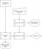
Rules of induction state that frequency of voltage induced in secondly coil should be same as that of passing through primary coil. So I was thinking if this property could be exploited to solve lazy governor issues on gen set once for all. The idea is that a a small transformer coil with diode in series to clip part of AC cycle due to reversed polarity causing on-off pulses in circuit. These pulses can be measured to determine current frequency. Based on feedback from Hz monitor, PWM to servo motor is supplied which in turn pulls throttle cable for until desired Hz is achieved. Off course there should be some delay like 1-2 second between sensing the Hz and taking action or else there will be a genset gone wild.

Even made a rough process diagram in visio. So much for visio 07, shame on me.
 

Attachments

  • Drawing9.jpg
    Drawing9.jpg
    49.1 KB · Views: 160
Last edited:
yes got your point..but as im not electronics engineer.. im asking for help here in designing it. Logic is all i have.

Mechanical governor run with the engine via belt and pulley. They usually come in two config, fixed speed and adjustable speed. What is does simply is pull throttle cable based on rotational speed which is not very accurate. The control factor here is engine speed. What im trying to do is to set controlling factor to Hz of voltage generated from genset so so output of genset will be much more stable and cleaner without all that irregular spikes in Hz.
 
Last edited:
I think you are trying to use the alternator output as a tachometer. The problem that I see is that the sensing circuit might not be able to differentiate between a legitimate RPM change and load changes (up or down). You are not wrong to say that Hz depends on RPM but my suggestion would be to measure RPM of the alternator shaft - and possibly the motor shaft if they are coupled where slip is a possibility. You probably want some pretty good resolution on crankshaft or alternator rotation - not just one pulse per engine rotation.
 
You can sense frequency the way you said. A wall wart transformer can bring the AC down to logic level. 12 V for CMOS or 5 V for TTL. Search this forum for tachometer, speedometer and servo circuits.
 
In my determination, using Hz as constant to control rpm produces best output. Out of three affecting factors ie: rpm, hz and volt. If one is to be appointed as control and second as variable then relation of Hz to rpm produces best output with hardly 10-15 volts drop between free running and peak load which wont make much difference. I mean your air con wont make a difference weather its receiving 220 volts or 240 volts.

An existing mechanical governor works on basis of tach feedback, just like Stevez mentioned. Which means despite being able to maintain constant speed versus load, it has no control over genset output and hence cannot make adjustment to affect them. And due to unregulated type head, output varies due to load condition even if rpm stays constant. Therefore the need to vary rpm based on some feedback from gen set output. A round of how different type of sensors will affect output.

RPM control based on Tach:
Voltage and Hz drop will be quite wide between low load and peak load condition causing fluctuation and not so stable supply to appliances.

RPM Control based on Voltage:
Under no or low load, desired voltage can be achieved at slightly lower RPM at the expense of major compromise in Hz. 230V@40Hz produced at 1400 rpm therefore we wont achieve correct cycles severely impacting performance of home appliances.

Whereas in a system where AC cycles are being used as clock to regulate engine speed, it may produce 240V/51.5Hz at 1450 rp, under low load and 220V/51.5Hz @ 1560 RPM at peak load. Slight drop in voltage is not likely to affect home appliance performance versus significant drop in cycles.
 
Last edited:
The gensets that use inverters, like specific models from the Honda, Yamaha brands are very stable.... to the point that they are approved for medical life support electronics. And they use a mechanical governor on the OHV engine! Gillette and Winco are also two brands that are industrial classed products providing ultra clean, stable outputs... again with a mechanical governor and high quality alternator, simplified regulation features. These few models of gensets I mentioned make up probably 1/20th of the avererage qualityn to pure garbage gensets out there. It's best to keep generators as simple as possible especially when they are called upon to run for very long times as well as remaining in various environments and long periods of inactivity. Complex electronics isn't favorable for acting as a band-aid fix in exchange for poor mechanical design and inferior product quality.
 
well to get this done electronically is just an itch of hobby u can say. Otherwise i don't care as long my air con runs fine. Btw, if anyone is interested this gen set is a ST type head directly coupled to 800cc natural gas automotive engine. Gas varies in pressure and impurities from main supply lines and that affects governor performance otherwise its quite capable.

With electronics, it would be quite simple..pull the throttle until desired Hz is reached. I don't think electronics involved here are complex. In simplest terms, a sensor detects Hz, an IC programed to display it on LCD segment and forward signal to servo controller. Kind of extension to home made AC Hz meter :)
 
Last edited:
theboss85 said:
well to get this done electronically is just an itch of hobby u can say. Otherwise i don't care as long my air con runs fine. Btw, if anyone is interested this gen set is a ST type head directly coupled to 800cc natural gas automotive engine. Gas varies in pressure and impurities from main supply lines and that affects governor performance otherwise its quite capable.

With electronics, it would be quite simple..pull the throttle until desired Hz is reached. I don't think electronics involved here are complex. In simplest terms, a sensor detects Hz, an IC programed to display it on LCD segment and forward signal to servo controller. Kind of extension to home made AC Hz meter :)

Not sure if electronic control would be classified as simple, There is tuning requirements so as to not over and undershoot control movement, however well within a micros capability. It's really a classic application of PID control..
https://en.wikipedia.org/wiki/PID_control

Lefty
 
Yeah I was about to say the same thing. Without a PID algorithm, the response will likely be WORSE than the mechanical governor. Otherwise, we have one or more of at least 3 problems:
1. The system will raise and lower the throttle too much when it sees the RPM change. The engine will surge forward as the RPM drops, then it pulls the throttle all the way back, then surges forward again. The system is unstable and oscillates.
2. The response is made slower to avoid oscillation, but then RPM lags as the load changes. You turn on a light and the gen slows down and it takes a sec or two to speed back up. In the meantime, the RPM is out of spec which is the only reason you wanted this project in the first place.
3. You lower the gain of the system, so an error of -2Hz will only raise the throttle slightly. It is possible that this won't be enough to compensate.

PID is the common, fairly simple, and effective solution. Even though the algorithm may be good, there are limits presented by the physical system. For example, if the RPM suddenly drops a lot, even providing max signal to the servo requires a number of mS to get to full throttle, and the engine may take another second to respond. So the RPM is definitely going to drop some.
 
Oznog raises good concerns. While it looks good on paper, it wont be effective without mind boggling complexity. You basically need an ECU which will talk to Hz based governor and control engine based on feedback. By slapping a servo on existing throttle cable, we are half way done with a crude form of ECU.
 
Using a 60 Hz reference and a phase detector (CD4046) will theoretically give zero error but the system is theoretically unstable. A lead-lag network will make it stable but I wouldn't know how to do that.
 
Russlk said:
Using a 60 Hz reference and a phase detector (CD4046) will theoretically give zero error but the system is theoretically unstable. A lead-lag network will make it stable but I wouldn't know how to do that.

I don't think it can ever be truely stable, as the response time of the engine is far too slow.
 
ehh i need 50Hz. Unless the servo is calibrated to open throttle in steps waiting 0.5-1 second between each step for Hz feedback, the response wont be stable and engine is more likely to surge between high and low. All this is against gonna bring the laziness of system equivalent to mechanical governor except we have more accurate control than mechanical.
 
Found out from gen head manual that 12V generated for self excitation of field can be varied using rheostat to alter output voltage where as Hz is purely a matter of RPM. Since it has 4 poles and output requirement is 51.5Hz, it takes perfectly 1545rpm to generate it. So a circuit to vary excitation 12V by sensing 230V output constant should suffice. Instantaneous response times and stability can be achieved since nothing mechanical is involved.

To be technically correct, its an AVR circuit which ships with gen head by default but due to its crappy quality and old technology, its considered quite junk.
 
Last edited:
Status
Not open for further replies.

Latest threads

New Articles From Microcontroller Tips

Back
Top