Continue to Site

Welcome to our site!

Electro Tech is an online community (with over 170,000 members) who enjoy talking about and building electronic circuits, projects and gadgets. To participate you need to register. Registration is free. Click here to register now.

  • Welcome to our site! Electro Tech is an online community (with over 170,000 members) who enjoy talking about and building electronic circuits, projects and gadgets. To participate you need to register. Registration is free. Click here to register now.

Solution required for Relay buring issue

Status
Not open for further replies.

Mohan nandish

New Member
Hi All,

We have a product to control 3phase agriculture motor.

We have deployed many units in the field and during rainy seasons our product is getting damaged.

I have shown device connection diagram in attached image.

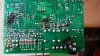
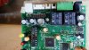
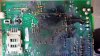
Damage is happening to Relay and all the semiconductor components on the board.

Relay contact tracks on the board is melting out and all the GND and VCC tracks on the board are damaging.

Images of the damaged boards are attached for reference.

You can find the data sheet of the relay in below link

https://voron.ua/files/pdf/relay/JQC-3F(T73).pdf

I suspect during thunder or lightning condition, very high voltage is striking the relay contacts.

Isolation between relay contact and coil is breaking down and this heavy voltage is passed to board through relay coil.

Please provide suggestions to solve this issue and protect relay from high voltage surges.
 

Attachments

  • connection diagram.jpg
    connection diagram.jpg
    168.7 KB · Views: 141
  • IMAG1.jpg
    IMAG1.jpg
    125 KB · Views: 140
  • IMAG2.jpg
    IMAG2.jpg
    111.2 KB · Views: 130
  • IMAG3.jpg
    IMAG3.jpg
    116.9 KB · Views: 125
What supply voltage does your board use, low voltage 5V?
What insulation rating do your relays have?

It is good practice to include transient voltage suppression (TVS) diodes on any harnesses subjected to lightning strike conditions, which would give a path to ground. I would place these near your relays to clamp any voltages coming back from the harness
 
I do not have time now to look but:
I think you do not have good spacing between 440V and (ground, signals, +5V, micro-computer, etc)
When water gets on the board .... boom.
No amount of TVS will help that.
 
Your design looks sensible, looks like your using a standard motor starter and connecting relay contacts into the start/stop button.
Really you need to find out whether the surge is getting in through the motor contactor side, or through the dc power supply socket.
If its the contactor then maybe you could try solid state relays with a high voltage standoff, if its the power supply then maybe you'll need a dc supply that has protection, like a industrial psu.
I dont think water would cause the microcontroller to get vaporised, but if it was then thats self explanatory.
If the lightening strike is close then you'll need some pretty good protection.
 
your data does not match up -- whitch is RY2 on connection diagram.jpg -- if it's the red wired and your contactor's "HOLD" strobes the RY2 melts e.c. ... i assume
 
Red traces are 440 VAC. (about 622V peak)
Yellow lines are where I think there needs to be more room.
upload_2017-6-9_18-14-57.png

From my experiance:
When a board is flat it will collect water. So, with high voltage, place the board standing up, so water runs away.
With high voltage I spray the board with a coating that insulates and repels water.
You used a "cutout " between the pins at the bottom of the picture. (connector) So you know what high voltage will do on a PCB.

I think the RED trace on the right side, sparked to the ground plane. (where the yellow line is) (This board)
Look up creepage distance for 600VDC.

The coil of your contactor will "fly back" or "kick up" when the little relays open up. The power line has 440Vac on it. Then added to that, the inductive kick of the coil. You could have 1000 volts for a very short time.
 
Last edited:
For certain contactor coils such as siemens, allen bradley, klockner moeller etc there is commerically available coil snubbers that are designed to attach directly to the contactor(for ac and dc), this is a neat and professional way to reduce coil kick, I've used these on a machine that uses very slow pwm via contactors for heating coils, the contactor coils are triggered from a plc's internal relay, and were burning out too quickly.
If you do another prod run maybe you could consider putting all the 415v switching stuff on a separate board.
 
Status
Not open for further replies.

Latest threads

New Articles From Microcontroller Tips

Back
Top