Continue to Site

Welcome to our site!

Electro Tech is an online community (with over 170,000 members) who enjoy talking about and building electronic circuits, projects and gadgets. To participate you need to register. Registration is free. Click here to register now.

  • Welcome to our site! Electro Tech is an online community (with over 170,000 members) who enjoy talking about and building electronic circuits, projects and gadgets. To participate you need to register. Registration is free. Click here to register now.

Solid State Relay with "low" load

Status
Not open for further replies.

tboydva

Member
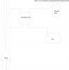
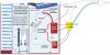
I thought I had this figured out, but the more I mull it over, I think I should get some "pro" advise. I have installed a "duo-charge" system in my boat which distributes charging to two separate batteries (starting and deep cycle) when the engine is running (https://www.balmar.net/page20-Duocharge.html). I also have a charger which works to distribute to the two batteries when hooked to an AC source. I assumed the duo-charge would be "confused" when the AC charger is going, so I used a switch to turn if off when charging at home. Knowing myself (and my forgetful ways), I thought perhaps an AC relay would be a good way to make sure when AC is applied to my AC charger, the power for the duo-charge is turned off. We have instruments with solid state relays and I like the fact that they're sealed and robust (which should be good for a rocking, watery, motion-filled environment like a boat). I thought I could split the mains power line and run the hot wire through the SSR input, then route the DC voltage wire through the switched side of the relay. The relay I'm thinking of using is the DC60SA3-B (**broken link removed**). My (crappy) circuit diagram is attached. Not sure if I'd need a protection diode in this scenario. In my readings and searching here and elsewhere (I wish forums would search quoted material or allow AND/OR searching), there seems to be an issue with SSTs and the amount of load switched. The duo-charge draws very little current and thus would represent very little load... Would this be a problem? Obviously I'm an electronics novice... Any help would be appreciated.
 

Attachments

  • relay.jpg
    relay.jpg
    118.3 KB · Views: 182
hi,
If I reading the DouCharge link correctly, it only controls the charge current to the Secondary battery [Start].
The Main battery [House] is coupled to the alternator output.?

How do you connect the ac mains charger leads to the battery system [when you have the DouUnit switched OFF].?
 
Last edited:
Ugh, sorry - I guess I should have stated that when I hook to AC, it's using a dual battery charger (the 4/4 unit): **broken link removed**.

This charger distributes current to each battery "as needed" so that both are fully charged (when hooked up to AC). It has a standard US 110V AC plug (which I propose to "tap"). I turn off the duo-charge when I plug into AC, but I know I'll forget at some point, so the relay came to mind as a way to short the power to the duo-charge any time I plugged into AC. Sorry to make it more confusing than necessary! Thanks for the response.

Tom

hi Tom,
I follow what you are trying to do.
Can you say what type of manual switch you using to switch On/Off the Duo.?
Are you running a pair of wires from the Duo on/off terminals to a switch.
 

Attachments

  • esp02 Sep. 03.gif
    esp02 Sep. 03.gif
    2.3 KB · Views: 165
Eric,

I have the duo-charge grounded with a wire to the (-) battery terminal. Then, I run a wire from my console which has a switch "between" the (+) battery terminal. I ran two 10 ga wires to the console from the (+) battery terminal and they terminate at a (+) bus. from there, I have a number of switches sending power to pumps, lights, etc. The switch from the duo-charge is on my console.

Now, as I re-read this it seems confusing. For all intents and purposes, the switch is between the (+) battery terminal and the duo-charge. I leave the duo-charge ground connected to the (-) battery terminal at all times.

Thanks! As I stated, these "sealed" relays are widely used on vessels as they are more immune to the harsh conditions.
 
Eric,
Now, as I re-read this it seems confusing. For all intents and purposes, the switch is between the (+) battery terminal and the duo-charge. I leave the duo-charge ground connected to the (-) battery terminal at all times.

Thanks! As I stated, these "sealed" relays are widely used on vessels as they are more immune to the harsh conditions.

hi Tom,
Obviously I am being cautious as we are talking of quite a bit of power!, also I must not damage your boat electrics.
Look at this image.

If its correct, I dont think the DC60SA3 is upto the job when the alternator is running.!

EDIT:

If the switch is going to be located in the position as drawn it has to be ON [SSR or Relay contact] when the alternator is running and it will have to carry the full charging current to the Start battery.
It will have to be OFF/Open when the mains charger is connected.
 

Attachments

  • esp03 Sep. 03.gif
    esp03 Sep. 03.gif
    22.5 KB · Views: 170
Last edited:
Eric,

Sorry - my description was obviously hard to understand! Perhaps this picture gives a better feel for what I want to do. The relay would only have a very small load (just to power on the duo-charge). Does this make better sense?

Thanks!
 

Attachments

  • relay.jpg
    relay.jpg
    192.9 KB · Views: 176
Last edited:
Status
Not open for further replies.

Latest threads

Back
Top