Continue to Site

Welcome to our site!

Electro Tech is an online community (with over 170,000 members) who enjoy talking about and building electronic circuits, projects and gadgets. To participate you need to register. Registration is free. Click here to register now.

  • Welcome to our site! Electro Tech is an online community (with over 170,000 members) who enjoy talking about and building electronic circuits, projects and gadgets. To participate you need to register. Registration is free. Click here to register now.

Solenoid driver: unwanted oscillation

Status
Not open for further replies.

earckens

Member
A solenoid driver is supposed to deliver a +/-800ms 12V pulse to the 12V DC solenoid after which the voltage drops to the solenoid holding voltage of 5V.

The circuit is activated by an opto-isloator; when supplying a 12V dc signal to X1 the circuit is activated (the optocoupler input remains high throughout). However I notice the following:
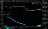
1. blue signal = Q1 base: about 400ms after activation a oscillation occurs at its base
2. yellow signal = IC1 pin 2: oscillation is transmitted through Q1 to this pin
3. when the blue signal drops to 0V then the transition occurs for the solenoid from 12V dc to 5V dc

Question: what causes the oscillation at the base of Q1?

EDIT: the solenoid draws 2A at 12V, 0.80A at 5V
 

Attachments

  • DS1Z_QuickPrint48.jpg
    DS1Z_QuickPrint48.jpg
    79 KB · Views: 119
  • solenoid_driver_v1.pdf
    22.3 KB · Views: 128
There is no pull down resistor at Q1 base, the base is effectively floating.

What is the purpose of C1?
Is it to create a pulse to trigger the 555 ?

I think you need to reconsider the whole R11 C1 R2 D2 circuit.

JimB
 
When C1 finishes charging, Q1 switches off slowly. At the threshold of conduction it will be sensitive to even slight changes of the base voltage, and hence prone to oscillate, e.g due to parasitics and noise. Try adding a resistor to ground from the right-hand end of C1, or replacing D2 by a pull-down resistor.
 
When C1 finishes charging, Q1 switches off slowly. At the threshold of conduction it will be sensitive to even slight changes of the base voltage, and hence prone to oscillate, e.g due to parasitics and noise. Try adding a resistor to ground from the right-hand end of C1, or replacing D2 by a pull-down resistor.
Just to be sure: a resistor between C1 and R2, to ground?
 
There is no pull down resistor at Q1 base, the base is effectively floating.

What is the purpose of C1?
Is it to create a pulse to trigger the 555 ?

I think you need to reconsider the whole R11 C1 R2 D2 circuit.

JimB
C1 is to provide a pulse to the base of Q1, in effect giving a down trigger pulse to TR (pin 2) of IC1.
 
10k between C1 and R2 to ground got pin 2 hence Q3 (IC1 output) to oscillate. A 10k between base Q1 and ground seems to have solved the oscillations apart from a few pulses: see attachement.
Trigger pulse to pin 2 now is just 50ms, still enough to activate the solenoid.
Any way to get rid of these last few pulses?
 

Attachments

  • DS1Z_QuickPrint49.jpg
    DS1Z_QuickPrint49.jpg
    77.7 KB · Views: 109
And C2 changed to 100nF, solenoid pulsed for 12ms, enough to pull the coil.
Yellow = pin 2
Blue = base Q2
 

Attachments

  • DS1Z_QuickPrint51.jpg
    DS1Z_QuickPrint51.jpg
    76.9 KB · Views: 123
Thanks a lot; just this: the 7802 when loaded with the solenoid drops to 3.8V (800mA) and even with big heatsink gets too hot; I ordered some 78S05 that can supply 2A.
That won't affect the heat generation very much.

You might consider going to PWM to reduce the current (about a 40% duty-cycle @ 12V) .
That won't generate much heat.
A 555 astable driving a MOSFET can do the PWM.
 
That won't affect the heat generation very much.

You might consider going to PWM to reduce the current (about a 40% duty-cycle @ 12V) .
That won't generate much heat.
A 555 astable driving a MOSFET can do that.
Very interesting; can you start me off with a basic design please? Thank you!
I would like to integrate this in my current design; heat indeed still is a problem, even at 5V and 800mA.
 
Pin 3 is the output.

Below is the LTspice simulation of a 555 configured as a PWM circuit with the duty-cycle controlled by pot U2.
It's set for about a 40% duty-cycle, giving an average current through a 4.75Ω solenoid of 0.93A.

upload_2018-3-27_12-6-48.png
 
D1 is not enough, you need an appropriate damping resistor in parallel with the solenoid to achieve underdamping. The output capacitance of the MOSFET and the parasitic capacitance of the solenoid form a parallel LC resonant circuit with the solenoid's inductance.

In order to calculate the damping resistor R you need to know the total parasitic capacitance C, or alternatively calculate it from the measured resonant frequency and inductance. Once L and C are known the critical R for a parallel RLC circuit is R = 1/2 sqrt(L/C), make sure you select a resistor that's lower than this.
?... there is no oscillation over the solenoid.
 
Is the same oscillation present at pins 4 or 8? if so, the regulator might be having troube adjusting to the sudden 2A draw. The LM7805 can handle up to 1.5A.
Another potential pitfall is the high value of capacitor C5, the LM7805 is specified for a smaller o.1uF output cap otherwise it may oscillate. See Fig. 18 and associated text in the data sheet.
 
Here's an alternative PWM approach, avoiding the need for a buck regulator :-
SolenoidCurrentControl.PNG

Q1 is a level-shifter.
U1a,b form a monostable circuit. C2,R4 set the width of the solenoid 2A pull-in pulse.
U1c is a gated PWM oscillator. R5 can be chosen to give an appropriate PWM duty cycle and hence hold current.
Q2,3 form a gate-driver.
C1 is to catch a power-up glitch.
 

Attachments

  • SolenoidCurrentControl.asc
    4.7 KB · Views: 85
Last edited:
Is the same oscillation present at pins 4 or 8? if so, the regulator might be having troube adjusting to the sudden 2A draw. The LM7805 can handle up to 1.5A.
Another potential pitfall is the high value of capacitor C5, the LM7805 is specified for a smaller o.1uF output cap otherwise it may oscillate. See Fig. 18 and associated text in the data sheet.
It is indeed an issue with the 7805 load regulation causing some output oscillation, but that is dampened after 2 cycled. The oscillation I had talked about before was solved by modifying the transistor base capacitor.
 
Here's an alternative PWM approach, avoiding the need for a buck regulator :-
View attachment 111903
Q1 is a level-shifter.
U1a,b form a monostable circuit. C2,R4 set the width of the solenoid 2A pull-in pulse.
U1c is a gated PWM oscillator. R5 can be chosen to give an appropriate PWM duty cycle and hence hold current.
Q2,3 form a gate-driver.
C1 is to catch a power-up glitch.
Hi Alec, with all due respect but what would be the advantage of using this over a 555 oscillator to drive a MOSFET gate?
 
Status
Not open for further replies.

Latest threads

New Articles From Microcontroller Tips

Back
Top