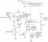
So, we're building a solar water disinfection system. For my part (electronics), I am controlling the pump (on/off) during a certain percentage of a 2 minute cycle (that repeats FOREVER) depending on the sunlight intensity (300-400nm is desired detection range). The microcontroller is controlling the pump. The inputs to the microcontroller are the float switch(es) and photodiode (in a circuit with an op-amp so op-amp output is microcontroller input). The outputs from the microncontroller are to the solid state relay (which controls pump via outlet (box?) and solenoid valve.
I'm sooo confused about the voltage supply. I'm using the Arduino (Atmega328 - assembled) - Duemilanove w/Atmega328 development board, on adafruit https://www.adafruit.com/index.php?main_page=product_info&cPath=17&products_id=68, it says it uses a 9 VDC wall adapter, could it use 12 VDC (or would that simply NOT fit)? I ask about the 12 VDC because the solenoid valve takes 12 VDC. Also, for the schematic I say everything is hooked up to a 5 VDC source (could that easily be changed to 9 or 12 VDC) & WHAT is that source (Oh YEAH, I think I remember now, it's hooked up to the board! NEVERMIND about where it gets the VDC from) Will/ Should those other parts be on a breadboard (when I get it working I plan on soldering the parts to a PC board)? Is anything missing?
- Solenoid Valve (2V025 1/4): I feel like I just plopped the solenoid valve in, does it need a resistor or anything?
- Solid State Relay: I picked the D2W203F because the pump draws an average current of 1A, but draws 2.6A when it starts up. I soooo DON'T get the solid state relay configuration.
WHAT is it hooked up to? I thought it is connected to a wall outlet (120 VAC) AND another outlet box (i got, nothing connected to it) that the pump will be plugged into, is that wrong? I liked the portable box because it seems easy to test with (portable), I can't be messing with the wall especially since in that room is not where we'll be testing, we're testing the complete system on the roof) AND how will I get the thing to turn on again if the power supply for the microcontroller and/or breadboard is plugged into that (once microcontroller tells it to turn off, how will it turn itself back on without power)? What are the voltage sources, it says + VDC & - VDC, especially the -VDC? From the development board AND what else? What gives -VDC?
- Float Switch (FLT133): I just got the float switches and they have 1 black wire/cord that's split at the end into two metal 'leads', is that right? How do I know what goes to VDC & what goes to ground or does it matter?? Most importantly, will it WORK? (I think I know, it doesn't matter) NEVERMIND that question. More importantly, with that configuration, the resistor's ok right? So, I didn't ask about the photodiode because I think that's set, can the op-amp be replaced with another 741? I'm just in the buying process and trying to stay under our littttle budget and get what I need at once to save on shipping. If you have any alternatives, I'd be open to hearing it. Plan on ordering everything by 9/25/09 the latest. Here are all the parts I'm planning on buying. Attached is a pic of an OLD schematic, just some parts names changed and the solenoid valve is an input to the microcontroller, that's all that's different. Thanks for all the advice and input.
Solenoid Valve (2V025 1/4): Direct Acting Solenoid Valve
Photodiode (PC2-2-TO52): https://www.electro-tech-online.com/custompdfs/2009/09/PC2-2-TO52.pdf
Solid State Relay (D2W203F): D2W203F Crydom Solid State Relays
Operational Amplifier (TLC741CP): **broken link removed**
Float Switch: https://www.electro-tech-online.com/custompdfs/2009/09/FLT133SpecSheet.pdf