Continue to Site

Welcome to our site!

Electro Tech is an online community (with over 170,000 members) who enjoy talking about and building electronic circuits, projects and gadgets. To participate you need to register. Registration is free. Click here to register now.

  • Welcome to our site! Electro Tech is an online community (with over 170,000 members) who enjoy talking about and building electronic circuits, projects and gadgets. To participate you need to register. Registration is free. Click here to register now.

Solar Setup & MBC help

abcdescott

New Member
Hi Everyone,

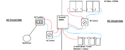
Looking for some help. I have this setup below Yes I have too little batter but hoping to get some more later on.

However I am looking for your oppinion and looking for some help, trying to find out what braker I should be using, the rating etc ?

I have tried to attach my solar write up hopefuly this will make sence. Feel free to ask any questions.

The reason I am using AMG batteries is I got them from work for free... Saving up to get Lifepo4 ones.
 

Attachments

  • piture.png
    piture.png
    88.2 KB · Views: 142
Circuit breakers or fuses should be rated at something just over the maximum working current of whatever circuit they are used in.

All cables must be rated at higher current than the breakers they feed or connect to!

You definitely need one in the battery connections, for safety - the batteries are the largest power source in the system!

That's in addition to the cutout positions you have marked.

The currents are not given, so I can't specify appropriate breakers..

ps. Watts are "flow" of power; capacity is WH (or KWH)
The total battery capacity, assuming it's 4 x 12V 95AH to give 48V, is 4.4KWH.
Thanks for your Message. The current from the Batteries is what I am struggling with tho. Not sure im just overlooking the correct math or not.
DC cables I am going to be using is 2AWG – 35MM.
Batteries are C20 12v 91.2Ah - Voltage together would be 48V.
I was hoping to get a breaker before the DC isolator - or after & a breaker from the battery's to the inverter.
The details for the pannel is VOC-43.5V ISC-12.68A
I was going to buy this, However I dont want to go too far above, where it might not trip the fue etc and do damage else where.


The C rating calculation I done retuned the amps as 1824amps so not sure about the math there.
 
I presume it means 43.3V with no load (Volts O/C) and 12.68A in to a short (Current S/C)?.
Ahh.. OK, that does make sense.. I was trying to get my head around the "Control panel" main unit having such figures...

I was seeing it left-to-right as a battery UPS, running from an AC fusebox & powering lighting panels.....


So, PV system:
The main unit is shown as 5000W. Based on that:

For 5KW out from batteries, the current will be somewhere around 140A. (The battery voltage could easily be as low as 40V under that type of load).

I'd probably use 160A GL NH00 rated fuses or a 160A circuit breaker in the battery connections.

Then 15A PV rated fuses for the solar panel set, eg. 10.38 size, in PV rated holders.

The maximum AC side current would be around 50A if it's a 110V system or 25A if it's a 230V system.

63A or 32A breakers there would seem reasonable.


The part that concerns me with that is the solar panel voltage.
>google<
OK, just found a manual for a "Growatt" 5000 controller.

As I suspected, the panel input voltage needs to be much higher, for that unit - the start-up threshold is 150V, then the working range is 120 - 430V


That may be for it to be in "MPTT" mode though, as it also states (Page 12):
"Open circuit Voltage (Voc) of PV modules should be higher than min. battery voltage."

43V is not enough in that case either, for a 48V battery pack.

A 48V lead-acid pack needs ~60V to fully charge, so I'd guess at least one more panel would be needed & possibly two or more, to get an useful power out??

(I'm guessing that the control unit has only buck conversion, based on the input specs?? eg. so the input voltage needs to be somewhat greater than the fully charged battery voltage?)

If! that is the correct unit?
WOW !! Some response that must be the best response I have ever had. You are amazing man, doing your own research into the growatt unit etc. Thanks !!

The system will be 240V (UK Homes)
The solar panels I have run at the attached so 43.6V each x 4 is 174v Minimum I am reading is 120V So hopefully should be fine there ... Lets hope :p

Lets brake it down into two sides, from the PV & the Battery.
I Would like to have a breaker between the battery and the inverter & Think to be safe I would like to have one from the PV as well - Just not sure if its before or after the DC Isolator

Currently Max will be the ~170V @ 12.68A

From the battery Currently will be 4 12v batteries in series with 91.2 Ah AMG battery's. With using 60% Depth of Discharge (DOD) that gives me roughly 2.6Kw of usable power from the batteries.

The part I am struggling with is how to calculate what the amperage would be from the battery at max discharge rate & if something was to overload what the fuse should be rated at so it doesn't fry the inverter or the batteries themselves.


Hope this kinda makes sence, ask any questions you need and I will try explain some more.
Just don't want to buy a breaker too small or too big. More worried about buying one too big tbh.
1684874166853.png
 
Found this ... Not sure why I didn't see this earlier.

So inverter W/battery V *1.25

This would be 5000/48*1.25 = (Rounding Up) 132A ?

But looking up this is all I can really find ? Max 64A ?


So On this page it says

What Size Fuse Between Battery and Inverter?

The size of fuse required depends on the size and voltage of inverter. There is a general rule or formula for this:

Continuous wattage/battery voltage * 1.25

So this would be the 132A Brings me back to the fact I cant find any MCB's that go to this rating.

When looking up online discharge and charge ratings of batterys.


This is still saying 1800Amp ?


I am trying to do all the math, but it keeps changing depending on what I am doing the calculations off... This is where i am struggling lol


1684876505968.png

 
The part I am struggling with is how to calculate what the amperage would be from the battery at max discharge rate & if something was to overload what the fuse should be rated at so it doesn't fry the inverter or the batteries themselves.
I gave that in the previous answer; around 140A for the max rated 5000W.

It's the wattage divided by the worst-case battery voltage under full load, so 5000 / 40 = 125A
The divide by 0.9 to allow for converter losses (They claim 90% efficiency).
That gives 138.888, so round to 140A.

160A is a common fuse rating.
 
"48V" is just the nominal battery voltage; it will be up to around 60V on charge and may be as low as 40V when discharging at high currents.

For high current fuses, look at the NH0 / NH00 side as I mentioned earlier; eg.


These should be suitable for the solar panels:

or
 

Latest threads

New Articles From Microcontroller Tips

Back
Top