Continue to Site

Welcome to our site!

Electro Tech is an online community (with over 170,000 members) who enjoy talking about and building electronic circuits, projects and gadgets. To participate you need to register. Registration is free. Click here to register now.

  • Welcome to our site! Electro Tech is an online community (with over 170,000 members) who enjoy talking about and building electronic circuits, projects and gadgets. To participate you need to register. Registration is free. Click here to register now.

solar panel and battery voltage selection:

Status
Not open for further replies.

earckens

Member
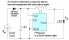
A little project (using rechargeable Ni-Mh batteries and a solar panel charger) needs 5V (using a AMS1117-5 LDO 5V regulator, minimum 6.0V input per its data sheet) to operate.
I have a 2W 9V solar panel, charging batteries through a 1A 0.4V forward voltage drop Schottky diode.
What is the best choice for battery voltage considering that a lower voltage will increase charging current, but also decrease usefull battery time when not charging (because lower battery voltage will mean faster discharge below 6.2V regulator requirement)?
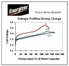
The Ni-Mh batteries come in 1.2V units, so 5 of these will give me 6.0V: just enough for the AMS1117-5. I read that the Ni-Mh discharge curve is quite flat meaning it will keep its output voltage over a discharge cycle. But enough or not for the AMS1117 requirement?

Edit 9/5/18: removed unrelated attachment
 

Attachments

  • AMS1117 5V LDO SMD voltage regulator.pdf
    92.9 KB · Views: 104
Last edited:
A Ni-MH cell is 1.2V halfway in a discharge but it is 1.4V to 1.5V when fully charged. You cannot even use 4 cells.
Since you do not have a charger circuit then your idea of blasting 1A of current into the unknown size of the cells would probably destroy them. The charger circuit must detect the full charge (not the voltage, but the temperature rise or voltage drop when fully charged) then turn off the overcharging or switch to a very low trickle charge.
Here is from the Energizer battery company Ni-MH manual:
 

Attachments

  • Ni-MH charging voltage.PNG
    Ni-MH charging voltage.PNG
    35.7 KB · Views: 163
A Ni-MH cell is 1.2V halfway in a discharge but it is 1.4V to 1.5V when fully charged. You cannot even use 4 cells.
Since you do not have a charger circuit then your idea of blasting 1A of current into the unknown size of the cells would probably destroy them. The charger circuit must detect the full charge (not the voltage, but the temperature rise or voltage drop when fully charged) then turn off the overcharging or switch to a very low trickle charge.
Here is from the Energizer battery company Ni-MH manual:
Thanks, but the 1A is not going to happen: the solar panel is 2W at 9V so max output current in theory is 200mA.
If the load is low impedance then at max current the solar panel output voltage will drop, and regulate itself the loadcurrent. Given that this panel will operate under full sun and the batteries are located in a closed box in the sun as well I suspect battery temperature will be less due to charging chemistry.
But I overlooked the fact that 1.2V is not charged. Your graph seems to indicate that the voltage goes from 1.5V fully charged to 1.2V empty; so 5 cells will go from 7.5V (still within the 9V panel charging capacity) to 6V when empty (barely within the AMS1117-5 uselful input voltage).
 
Just connect the 4,5,6 cells in series to the solar panel. And the diode is not necessary.
Voltage regulating is the method to recharge Pb cells, not the way to charge NiMh cells.
 
An old Ni-Cad cell cools as it charges but a modern Ni-MH cell heats, try them both together and feel it. You will be cooking your Ni-MH cells like in my solar garden lights.
The 2W/9V solar cells produce 222 mA at noon on a sunny day. The current averages about 150mA for 10 hours per day in summer. If the battery is AA size 2500mAh then it half charges in one sunny day. An AAA 850mAh battery will overcharge and not last long.
The diode is VERY important to keep the battery from discharging into the solar cells at night. All my solar garden lights have it:
 

Attachments

  • solar garden light details.png
    solar garden light details.png
    24.3 KB · Views: 126
After audioguru posted his message #2 I searched some more info (attached). The current batteries are 1900mAh, for the time being 5 of them; in series. But my load is 50mA only, during 2 seconds, once every 20 minutes. So total consumption over 24h = 144 seconds at 50mA = 0.002Ah/day. And where it will be used there is daily 10h sunshine in summer. So even with 1 hour of sunshine the batteries are charged 0.150Ah/day. So more likely overcharging may become an issue?
 

Attachments

  • NiMH nickel metalhydride application manual.pdf
    410.2 KB · Views: 194
1900mAh is fairly low for a modern AA Ni-MH battery cell. Chinese ones? Modern ones hold a charge for 1 year, yours do not need a trickle charge.
The average of 150mA for 10 hours each day is much more than the 1/40th trickle charge recommended by Energizer and Sanyo/Panasonic. 1900mAh/40 is only 47.5mA for a recommended trickle charge.
https://www.nkon.nl/4-aa-eneloop-batterijen-bk-3mcce-in-case.html
1900mAh should enable the load to bridge covered days, and/of spring and autumn usage; I hope.
 
The diode is VERY important to keep the battery from discharging into the solar cells at night.


(A)------|>|---|>|---|>|---|>|---|>|---...---|>|---|>|---|>|---|>|---|>|--- (K)
30 diodes X 0.7Vf = 20Vf


(+)----------------------------------13.8V battery-----------------------------(-)


Above is a representation of a 'nominal' 12V solar panel and a fully charged '12V' battery.

Connecting (+) to (A) and (-) to (K) as in above : current will not flow at dark as the battery is less than 20V.


It is the representative case of why the lack of a blocking diode in series with the solar panel does nothing to prevent current flow when dark. Simply the battery voltage does not overcome the panel Vf. The properties of the panel itself do the prevention.
In all cases of having a battery connected directly to solar panel, the sum of 0.5V generation per cell is less than the 0.7Vf per-diode presents, implying the battery will never overcome the panel Vf.


For a garden light:

(A)-----------------------|>|---|>|---|>|---|>|-----------------------------(K)
4 cell solar panel = 2V = 4 diodes x 0.7Vf = 2.8Vf

(+)--------------------------------1.4V charged cell-------------------------(-)

Connecting (+) to (A) and (-) to (K), current will not flow at dark as cell is less than 2.8V
 
I tested two different solar panels from garden lights. Both produce 2.60V in sunlight with no load and both conduct when dark. They even conduct a little in darkness with the 0.2VDC from my multimeter Ohms test.
That is why all solar garden lights have a diode to prevent the battery from discharging into the solar panel at night.
After three weeks of testing I get following results with this setup:
1. 9V 2W solar panel
2. 5x AA 1.2V NiMH batteries (Eneloop 1900mAh)
3. microcontroller and ancillary circuitry, 400 msec active @35mA, 15 minutes inactive (sleep) @0.050mA after a 5V LDO regulator (LM1117)
4. 1A Schottky diode between solar panel and batteries
The batteries charge to about 7.3V during daytime, the box containing the electronics and batteries gets to about 40°C, at night slow discharge from full load to about 6.5V in the morning with an inverse power distribution (as you have with capacitor discharge).
My conclusions:
1. a protection diode is necessary to protect the solar panel and prevent reverse discharge through the panel, and only looses about 0.4V forward
2. the 5V LM1117 needs about 5,8 to 6V to function, the 5 batteries even when partially discharged still provide more than 1.1V each, and when fully charged give about 7.2V total
3. the 9V solar panel gives about 9V in full sunlight, unloaded; connected to the batteries the charging voltage never goes higher then 7.3 to 7.4V. In morning daylight without sun the panel charges at about 7V.
4. given the extreme low current consumption of the load I believe that the difference in voltage between charged and half empty batteries is enough to keep everything running at night and allow the panel to fully charge the batteries in daytime.

This is just a little project but a nice learning tool for future use in larger consumers.

Edit: by the way audioguru, this project is using your fantastic moisture measurement oscillator circuit from several years ago.
 
Sometimes the weather is cloudy for one week. Then some of my solar garden lights light for less than one hour at night. Does your pile of AA battery cells not get charged enough when your weather is cloudy for many days?
Some of my solar garden lights use a Western 2300mAh AA cell but many use a Chinese 300mAh (actually 200mAh) AAA cell. The new Chinese Ni-MH AAA cells are much better than their old Ni-Cad AAA cells.
The batteries are from a Panasonic subsidiary, and optimized for very frequent charging cycles, they cost quite a bit. As far as charging is concerned, with this amount of discharge (average of 35mA 0.02% of the time, the rest at 0.04 or less mA) I think there is not much to fear of cloudy days, especially since these units will be installed in Southern France.
The little circuit I borrowed from you (attached) is a genial piece of hardware: robust, very accurate (I get about 0.05% accuracy and repeatability when doing highly precise microcontroller rmeasurements), and fairly easy to tune once the habit is there.
 

Attachments

  • 4kHz conductive AC schematic and parts list EDAboard_353365.png
    4kHz conductive AC schematic and parts list EDAboard_353365.png
    27.1 KB · Views: 110
Last edited:
Sanyo (now owned by Panasonic) invented the Eneloop chemistry for Ni-MH battery cells but now many battery brands use it and are listed as "pre-charged" and "holds a charge for one year". Here in Canada I buy ordinary price Energizer and Duracell Ni-MH battery cells that are made in Japan, maybe by Panasonic.

I found the original defective Plant Watering Watcher circuit online and fixed it 13 (!) years ago. I am glad to hear that you still use it and like it.:)
 
Status
Not open for further replies.

Latest threads

New Articles From Microcontroller Tips

Back
Top