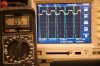
But Vout is determined by the duty factor. The FET turns on and energy builds up. The FET is switched off. The secondary winding discharges into the diode & output. The Vout value is simply Vin*(D/(1-D) times the turns ratio. In other words Vout is determined by Vin, the turns ratio, & the duty factor. To get high values of Vout, a large duty factor is needed, or turns ratio. SO it definitely matters as to duty factor.

")