Tykulcsar666
New Member
Hello,
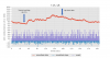
I posted a question a while back regarding this simple circuit to measure skin conductance. I've been getting data for the project and it seems to be vaguely measuring conductance, but the data is noisy and the peaks aren't as distinct as they should be. I have an example of some data below.
Other than using better electrodes for sensing, looking to see how I can optimize hardware to eliminate noise. There is a 0.5 Hz low pass filter, but not sure of other ways to make the circuit more robust.
Any help would be very much appreciated!