Continue to Site

Welcome to our site!

Electro Tech is an online community (with over 170,000 members) who enjoy talking about and building electronic circuits, projects and gadgets. To participate you need to register. Registration is free. Click here to register now.

  • Welcome to our site! Electro Tech is an online community (with over 170,000 members) who enjoy talking about and building electronic circuits, projects and gadgets. To participate you need to register. Registration is free. Click here to register now.

Size matters

Status
Not open for further replies.

camerart

Well-Known Member
Hi,
I am making a PCB with a PIC onboard. Previously, I have used a 40PIN 18F4520 for projects, but lately I've ventured into Surface mount components. I ordered some SM 18LF4520 for the job, looking as carefully as I could at 'all' of the specifications. I didn't notice the actual size. Here's a photo of the difference. We'll soon find out if I can solder them or even make those fine tracks on the PCB.

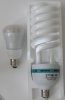
Likewise, my son ordered a brighter light bulb for his lamp, Here's a photo of his mistake too:wideyed:
Camerart.
 

Attachments

  • 18LF4520 size.gif
    18LF4520 size.gif
    1.4 MB · Views: 158
  • Bulb size.jpg
    Bulb size.jpg
    197.2 KB · Views: 141
Dave Jones will show you how to solder it. Look at 13:58 of the video.

 
It's not the size that concerns me when I order, it is the pitch of the pins -- if any -- that I look at. I do not go below 0.5 mm and prefer 0.65 mm or larger. Leadless is OK so long as there is exposed metal on the sides of the chip to wick the solder, e.g., 16-QFN. One problem apart from lead/contact spacing is heat sinks in the middle. They can be difficult to say the least to hand solder.

Here is a useful reference for Microchip packages: https://ww1.microchip.com/downloads/en/PackagingSpec/00000049BQ.pdf

While the data therein may apply to other manufacturers, it is still advised to check for a specific chip.

John
 
We've all done it. It's a standing joke at work that I'll order something that looks right in the picture but is completely the wrong size.
SOT23 vs. SOT232 is a classic...
 
It has not been mentioned yet in this thread, but adapters are available for many of the surface mount sizes. One brand Schmartboard (https://schmartboard.com/ ), despite the hokey name, has milled grooves for what's left of the leads. They facilitate alignment and soldering. I have no relationship to that company, but I have used its boards for QFN chips.
 
The key to soldering small SMT components ARE THE TOOLS.
Specifically, a good temperature controlled soldering iron with a very fine tip, thin gage solder, and a sturdy board vise to hold it steadily while you manipulate it. Don't forget the tweezers.

And....unless you have an eagle's sharp eyesight, a good illuminated magnifying glass is also a must. I cannot overemphasize the fact that the magnifier has to have good optics, there are many cheap e-bay stuff that have terrible optical characteristics which render them useless.
An option is an USB microscope. Google the term.
 
We've all done it. It's a standing joke at work that I'll order something that looks right in the picture but is completely the wrong size.
SOT23 vs. SOT232 is a classic...
Hi T,
It would be handy if there was something in the image to help guage the size.
C
 
Hi all,
I watched the video, very handy.
Previously, I have a USB microscope, plus a work station with hot air blower, also some solder paste.
I was hoping to first clean the PCB, then try to gauge the correct amount of paste, then heat till the component drops through the paste.
C.
 
yes, i just recall how difficult is with only two hands to keep all components at the position (relative to PCB glass fiber surface elevated pads) provide the flux and do a precision solder on leads you barely guess/distinguish the v(x,y,z)-s
https://hackaday.com/2014/01/05/testing-the-limits-of-home-pcb-etching/
where i live the access to HNO₃ might be difficult (with no much chemist experience) + i won't even consider setting up an extended fire risk at my house/apartment
Hi C,
I've never used solder paste with such small components, but hopefully, I will only need two hands (my full complement) one for the pin and one for the hot air blower, having cleaned the PCb with liquid flux beforehand.
I'll let you know how I get on. I'm still struggling routing the PCb at the moment.
C.
 
It's a lot less scary once you've done it a few times. Use the Flux, Luke...
 
wow, a 135w CFL bulb should be comparable to about 700w incandescent i guess. That is way too much light for just about any room.
 
wow, a 135w CFL bulb should be comparable to about 700w incandescent i guess. That is way too much light for just about any room.
Hi K,
After further reading, it was explained that the bulb is not tuned for full capacity, but set to 65W.
It is bright.
C.
 
??? or gets blown off by the hot gust
Hi Ci,
After carefully soldering the Barometer modules, and removing the holding down pin, I noticed that the solder wasn't quite 'soaked' so I aimed the hot air at it again, without holding. When the solder melted, the module actually moved towards the jet, and centralised better.
C.
 
we can suppose there are two factors behind it (•) the melted first direction having least resistance/drag (••) the net surface tension combined with the weight of the chip with the number of pins and the symmetry of the chip ?? also the intensity of the air flow - - - just a best guess
 
Pretty sure it's mainly surface tension that does it.
 
Pretty sure it's mainly surface tension that does it.
Hi,
I've read a few times that it is surface tension, but I was surprised that it moved towards the jet, as I was aiming at the side. I didn't actually think the 'far' side PADs solder would melt.
C.
 
Status
Not open for further replies.

Latest threads

New Articles From Microcontroller Tips

Back
Top