Continue to Site

Welcome to our site!

Electro Tech is an online community (with over 170,000 members) who enjoy talking about and building electronic circuits, projects and gadgets. To participate you need to register. Registration is free. Click here to register now.

  • Welcome to our site! Electro Tech is an online community (with over 170,000 members) who enjoy talking about and building electronic circuits, projects and gadgets. To participate you need to register. Registration is free. Click here to register now.

SIPO shift register 74164

Status
Not open for further replies.

Mr CCE

New Member
hi there,

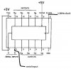
recently I've been trying to use 74164 to obtain separated bits of a byte and I've connected this IC as the attachement shows.However I'm getting all ones on all of the output, even when I change the byte(serial input).

so could anyone help?please?

thx in advance.
 

Attachments

  • SIPO.JPG
    SIPO.JPG
    20.8 KB · Views: 4,200
The datasheet states that the 2 inputs are ANDed to provide the data to the SR. Either connect one of the inputs to Vcc, or connect both inputs together.
 
Last edited:
The results.....

Hi there,

I tried to join the two inputs A and B but the result is still the same: I'm getting either all zero outputs or all ones, eventhough I'm changing the byte value entered (considering same clock).

I also tried placing another IC just to make sure that the original is not burnt or something, but guess what: it's the same. Maybe it's an error in connection 'cause this is the first time I use this IC.

regards.:rolleyes:
 
how are you entering the 'byte value'? Once you've clocked in the 8 bits, you have to stop the clock or else all the bits will be shifted out again. When you want to shift in the next 8 bits, apply another 8 clock pulses in conjunction with the 'byte value'/
 
What I've been doing so far....

Hi there,

Well, what I've been doing up till now is to connect the byte in question- generated by DIP switch inputs connected to a shift register (74165 parallel in-serial out) driven by a clock generated by the 555 timer, to another shift register 74164 (serial in-parallel out) driven by the same clock.The clock's always connected like this, but doesn't that mean that the output of the 74164 will always correspond to the dissassembled byte? Otherwise When do I stop applying the clock?

Your advice on this please?
:)
Thanks very much for any help.

regards.
 
Feel free to post your schematic of the circuit that you're using now.

With the parallel-in-serial-out (PISO) SR you need to load the data into the latches/SR by using a falling edge (a low pulse) on the parallel-load (/PE) pin. Then the 8 bits of data are shifted out using 8 clock pulses. if you apply any more clock pulses, then you will start shifting out unwanted values.

With the serial-in- parallel-out (SIPO) SR you can use the same clock and the output serial data from the PISO is fed into the serial input of the SIPO. With each of the 8 clock pulses, data will be shifted into the SIPO and displayed on its outputs. if you apply any more clock pulses, then you will start shifting in unwanted values.

So, pulse /PE low, apply 8 clocks. Repeat whenever you wish to update the output values.

Just so that you can see what's happening, slow down the 555 timer to maybe 1Hz and connect an LED to each of the '164 outputs. Apply some 'byte' pattern to the PISO parallel inputs, pulse /PE and see what happens at the LEDs.

Have a look at these interactive shift register basic tutorials. You can click on the control lines to see the data get shifted through.
**broken link removed**

**broken link removed**
 
Right on...

Hi there,

Thanks for the link, the animation was quite educational;) but there's something I wanna make sure of:

- How to know when to apply the clock and when to stop it? 'cause obviously running the serial data in and the clock all the time doesn't seem to work? so I have to syncronize by adding extra pulses so that a microcontroller will know when to start applying the clock and its program will know when to stop.

Is there any other -easier:D- way to accomplish this?

thx
 
what microcontroller? draw a diagram of what you're talking about.
 
Don't do it that way.

The pic16f877 has a "shift register" built in, also known as the USART, which allows you to transmit and receive serially and also puts framing in so that the receiver knows where it is up to. Or you can use a pin and bit-bang the incoming signal if you wished to use some transmission encoding scheme of some sort.
 
Already on it...

Hi there,

Thanks for the quick reply.
Well, I've already started on using internal USART(or UART for 16F877A)
and I've simulated the program on PIC simulator IDE and it worked. However there's one question I'd like to ask.

If I send, using the SEROUT statement, a byte variable of value "64", and on the reciever side I use the SERIN statement to retreive it, and then display this variable on portc-already configured as output port- will I obtain the value 64 on portc? I'll post the code I've written so far and if you could tell me what's wrong I greatly appreciate it.

regards.
 

Attachments

  • softUART testingRx.txt
    348 bytes · Views: 224
  • softUART testingTx.txt
    390 bytes · Views: 172
Ah that one......

hi there,

thx for the quick reply,

I was actually confused and frustrated at that time I didn't think about what I was writing, anyways I got it done!

The problem was in the SEROUT statement of the output program, where I initialized the variable to be 64, " i = 64 " and then in the SEROUT statement I entered " #i " instead of just " i " , it was totally a syntax mistake, 'cause adding # displays the decimal value of " i " instead of 64.

THANK GOD I was so happy when I succeeded, I received a "64" on the output!!! Phew!!

But there's a but. I'm now adding an RF module but before it is of course the codec (encoder on Tx, decoder on Rx) and it needs two inputs (obviously!):

The clock and data. Is the clock period corresponding to the " Define SEROUT_DELAYUS = 500 " ? 'cause this delay corresponds to 1KHz, so does that mean I have to use a 1 KHz clock for the encoder/decoder?

thx for any future help.

regards.
 
The clock and data. Is the clock period corresponding to the " Define SEROUT_DELAYUS = 500 " ? 'cause this delay corresponds to 1KHz, so does that mean I have to use a 1 KHz clock for the encoder/decoder?
No.

Have a look at the following from (**broken link removed**) - in fact you could read that page as there is some background info on programming in that language.
SEROUT statement uses SEROUT_DELAYUS parameter that can be set by DEFINE directive and has default value of 1000 microseconds. This defines the delay interval before a character is actually sent to the port and it is used to increase the reliability of software SEROUT routine.
 
About UART...

hello,

Thanks for the link but actually these help examples are available once you install the simulator, but thanks anyway.

The problem is that I'm using an RF module that accepts input frequencies of 1KHz to 4KHz and I'm using the statement "DEFINE SEROUT_DELAYUS= 5000"
so how is that related to the transmit frequency? 'cause I didn't quite understand what "delay interval before a character is actually sent to the port" means? is this 'delay' equal to a bit duration?:confused:

thx a lot in advance.

regards.
 
Last edited:
A new approach....

Hi there,

Lately I've been recommended to use encoding/ decoding IC's that are very easy to use, namely: MC145026/7. I downloaded the datasheets and things are looking promising, and I got a very positive feedback from people who are still using them.

If you're familiar with them please give me your advice and any useful directions. The encoder 145026 accepts five addresses and four data inputs/pins, and transmits them serially. Be my guest and do check the datasheets if you're not familiar with them, I could use a helping hand;)

thx a lot for any future assistance.

regards.
 
Last edited:
Please read the manual/user guide that came with your compiler. For the SERIN/SEROUT command, you need to specify the baudmode parameter (for which you have put 9600) to control how fast the bits are sent, their polarity and other properties. I've attached an excerpt from the manual that shows some example values for different baud-/bit-rates.
 

Attachments

  • baudmode.gif
    baudmode.gif
    13.3 KB · Views: 263
About UART.....

Hi there,

Thing is, I tried different baud modes but the result is the same: I'm not getting the result that I want, which is to securely send data and almost acurately receiving it; obviously the system needs some sort of a codec.

I've been spending all my time on these new IC's and the outcome is fantastic; data is successfully transmitted and received! no errors!

Thanks for any future help friend!!

regards.
;)
 
Status
Not open for further replies.

Latest threads

New Articles From Microcontroller Tips

Back
Top