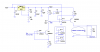
I have used the circuit presented by Roff and it works except for one little problem. When I adjust the pot to set the output to 4.00 mA, I sometimes am unable to set to to 4.00. On the board I am making now, it only goes to 4.02. Would it work to lower the two 10K resistors and use a bigger adjustment pot?? I looked at the AD694 and it looks like it would do the deed but I already have 15-20 boards in use and want to stay with the same design. Thanks!