Well not really singing plants as such, but i'll explain that in a second.
Firstly im new here so big hello and to give you a little info about me... I confess I know very little about electronics, i learnt a little as a kid and curently trying to catch up reading as much as i can at the moment but could use a little help (ok well maybe alot).
Im curently working on a university project, i study sound arts and design and i am looking to create a sound instalation/performance piece based on responses from plants.
This is inspired by some work done in the 60's and 70's that shows when a plant is stimulated the resistance varies and i will be using this to trigger and alter parameters of a sound. I will be using an arduino board to input voltage changes into max/msp where i will convert that data into sounds. I have that all sorted but i need help with the electronics.
Now here is where i am struggling. I need to make a device that will measure resitance variations in the plant tissue. When a plant is stimulated (in this case physically) the resistance varies (much like in a person).
Now i will not be marked on the electronics as my marks are on the concept and how is sounds so i am free to get assitance with the electronics, how ever any help i do recieve i am more than happy to credit the individuals should anyone wish.
I was looking at making a weatstone brige and an amp, but i eventually stumbled upon this article which seems to be alot of the work done for me!
The article will give you a better overview of what im talking about.
If you could have a look at the second link. It is the schematic for the system.
**broken link removed**
**broken link removed**
**broken link removed**
**broken link removed**
**broken link removed**
**broken link removed**
**broken link removed**
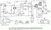
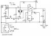
Looking at the schematic here where i am struggling
1. The input output polarizer. How does this work? I dont really understand how it would be wired. Its confusing me quite a bit, why have the tracks comming from the electrodes (bp 1 and bp2) been crosed over each other?
2. How viable is this in terms of part avalibility? I think the ic might be a little out of date but shouldnt be to hard to find a sutible replacement. Any advice as a whole?
3. I need the output to be in a voltage range of bewteen 0-5volts. A range of 0-1 would suffice though. Where would be the best place on the schematic for me to take the output to be sent into the arduino? At the dc recoreder or the audio output? Im asuming the dc recorder but im not sure what voltage range it will be outputing.
Im sure there will be plenty more questions to come but thanks for reading this far. If you need any clarification on anything just ask and any help, advice or ideas would be much apreciated")
Steve
Firstly im new here so big hello
and to give you a little info about me... I confess I know very little about electronics, i learnt a little as a kid and curently trying to catch up reading as much as i can at the moment but could use a little help (ok well maybe alot).Im curently working on a university project, i study sound arts and design and i am looking to create a sound instalation/performance piece based on responses from plants.
This is inspired by some work done in the 60's and 70's that shows when a plant is stimulated the resistance varies and i will be using this to trigger and alter parameters of a sound. I will be using an arduino board to input voltage changes into max/msp where i will convert that data into sounds. I have that all sorted but i need help with the electronics.
Now here is where i am struggling. I need to make a device that will measure resitance variations in the plant tissue. When a plant is stimulated (in this case physically) the resistance varies (much like in a person).
Now i will not be marked on the electronics as my marks are on the concept and how is sounds so i am free to get assitance with the electronics, how ever any help i do recieve i am more than happy to credit the individuals should anyone wish.
I was looking at making a weatstone brige and an amp, but i eventually stumbled upon this article which seems to be alot of the work done for me!
The article will give you a better overview of what im talking about.
If you could have a look at the second link. It is the schematic for the system.
**broken link removed**
**broken link removed**
**broken link removed**
**broken link removed**
**broken link removed**
**broken link removed**
**broken link removed**
Looking at the schematic here where i am struggling
1. The input output polarizer. How does this work? I dont really understand how it would be wired. Its confusing me quite a bit, why have the tracks comming from the electrodes (bp 1 and bp2) been crosed over each other?
2. How viable is this in terms of part avalibility? I think the ic might be a little out of date but shouldnt be to hard to find a sutible replacement. Any advice as a whole?
3. I need the output to be in a voltage range of bewteen 0-5volts. A range of 0-1 would suffice though. Where would be the best place on the schematic for me to take the output to be sent into the arduino? At the dc recoreder or the audio output? Im asuming the dc recorder but im not sure what voltage range it will be outputing.
Im sure there will be plenty more questions to come but thanks for reading this far. If you need any clarification on anything just ask and any help, advice or ideas would be much apreciated
Steve
Last edited: