Continue to Site

Welcome to our site!

Electro Tech is an online community (with over 170,000 members) who enjoy talking about and building electronic circuits, projects and gadgets. To participate you need to register. Registration is free. Click here to register now.

  • Welcome to our site! Electro Tech is an online community (with over 170,000 members) who enjoy talking about and building electronic circuits, projects and gadgets. To participate you need to register. Registration is free. Click here to register now.

sine wave to square wave

Status
Not open for further replies.

jay543_uk

New Member
Hi all
im doing a project for my car which has different sensors going into a 16f876a pic and displaying them on a lcd display, my problem is i dont have a speed sensor but i do have a unused abs wheel sensor which pics up on a 32 tooth ring on the drive shaft.
the abs sensor has two wires and produces a ac signal as the toothed ring rotates in front of it
the problem is that the voltage produced increases from 0 to 300v as the frequancy ie wheel speed increases.(frequany could be as high as 1khz)
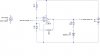
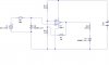
i was looking to use a schmitt trigger to change the sine wave to a 5v square wave.
how would i connect the abs sensor and also how would i stop the sine wave voltage getting to high that it damages the schmitt trigger, i need to do this with out effecting the frequancy.

iv attached the schmitt layout i plan to use
 
layout of schmitt
 

Attachments

  • abs2square.JPG
    abs2square.JPG
    17.4 KB · Views: 1,078
I can offer you a different solution, if you like. You could use an Op-Amp in open-loop mode (no feedback) so that it has a gain of >100,000. Then it'll try to make your sine wave >100,000 times bigger which in reality means it'll shoot off and stop short of the power supply rail. The result is an approximate square wave.

Brian
 
Ok so if the ABS sensor has a 300V output (really?) then I guess you need to step that down first. There's a few ways you can do it, I think I'd use a step-down transformer.

Brian
 
the thing is at slow speeds say 10 miles per hour , the voltage will only be about 1.5v

if i step that down will it not trigger the op amp
 
Oh right I see. I'd have thought the frequency would change relative to speed, but not the amplitude? Usually it's one way or the other, not both. Are you saying that both the frequency AND amplitude change with respect to speed?

Brian
 
well at about 10 mph i was getting a reading of about 1.2volts on a multimeter set to a.c, i then span the wheel at about 20mph and the reading on the meter went up to about 2volts.

i found a web site that a some bloke had done the same sort of thing and he said that he had recorded voltages up to 300volts at high speeds and so put a capicitor down to ground to make the 4v peak to peak.

dont understand what he means
 
perhaps loading it with the capacitor takes the voltage down, as it is its like an unregulated transformer, you could use a zener ? in paralel so that if under say 5 V it stays unchanged and over it is cut off
 
ok a zener could work, how do i connect the abs sensor to the schmitt trigger. do i need to put a diode on the input side to stop -volts passing and what do i do with the other wire, ie just connect it straight to the 5v battery earth or do i need to put a diode on that side to.
 
just tested the sensor today which i believe to be a inductive type sensor and at about 100 mph it showed a ac reading of about 10volts

believe my schmitt trigger should handle that and only put out a 5v square, am goin to just have a zener diode to protect the schmitt just incase the volage does get high

im still not shore how i connect my inductive sensor in to my schmitt, ie the live goes into pin 3 but what do i do with the other wire.

can this just connect to my 5v earth or do i need to add a diode to stop negitive signals going down that wire into the 5v earth
 
would this circuit work or would it mess up the negative side of the 5v power sourse to trigger
 

Attachments

  • abs2vs.JPG
    abs2vs.JPG
    17.5 KB · Views: 409
jay543_uk said:
would this circuit work or would it mess up the negative side of the 5v power sourse to trigger

I thought you said your sensor outputs 0 - 10V approx. Are you saying that infact it outputs a sine wave that sits on ground and oscillates positive and negative?

If that's the case, why not use two zeners in series (facing away from each other) with a series resistor so that the a.c. signal is clamped at one diode drop above and below the zener voltage?
I'm not sure about your value of 10M for the series resistor though...

Also one other point, in your current arrangement the output signal is inverted - is this ok?

Brian
 
the sensor is a inductive sensor which i believe produces a sine wave signal which positive to negitive on a scope, iv only looked at the voltages on a multimeter set to ac.

i put the 10m resistor in because i'm planning on fitting a abs system to the vehicle so the sensor will be being used by the abs control module and i didnt want to interfear will the signal at all, thats why i used a very high resistor.

when you say two diodes do you mean one on each wire of the sensor or both on the same line.

sorry if im confusing people, im just learning as im going along and just trying to work out if its posible before bying parts

thanks for any help
 
The resistor should be there to limit the current through the zener diodes, therefore the value needs to be calculated with that in mind. For details on the arrangement I was talking about, see the following link:

**broken link removed**

Some way down the page there's a section on clamping which will interest you.

Regarding your concern about loading the control module, if this bothers you the best way to go about it is to use an Op-Amp with Unity Gain. The input of the op-amp itself is very high impedance and therefore should have negligible effect on your control module. The output of the Unity Gain buffer can then drive your circuit.

Brian
 
had a little look at that site and seems the best way of stopping the sine wave voltage going to high, iv attached another diagram.

check that 1 out and see if you think it will work

cheers for all the help, i'm a beginner at electronics and just making it up as i go along.

thanks jason
 

Attachments

  • abs2vs.JPG
    abs2vs.JPG
    24.4 KB · Views: 244
noticed a problem already with the diagram, the 5v battery into the regulator should be a 12v battery and it should be a 5v output from the regulator .
 
Status
Not open for further replies.

Latest threads

New Articles From Microcontroller Tips

Back
Top