Continue to Site

Welcome to our site!

Electro Tech is an online community (with over 170,000 members) who enjoy talking about and building electronic circuits, projects and gadgets. To participate you need to register. Registration is free. Click here to register now.

  • Welcome to our site! Electro Tech is an online community (with over 170,000 members) who enjoy talking about and building electronic circuits, projects and gadgets. To participate you need to register. Registration is free. Click here to register now.

Simulating a ZVS circuit/Royer oscillator design

Status
Not open for further replies.

ronniebra

New Member
Hi there,

First off I wanted to thank all of you for a previous thread that helped me get this oscillator going.

I am able to get oscillations - but it's not what I expected.
Screen Shot 2019-03-25 at 12.04.38 AM.png
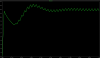
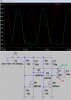
With this design I expected the current through L3 to be a half-wave sin (no negative portion) yet the output is a full sinwave. Also, taking out the capacitor doesn't give me a square wave, but rather, a junk measurement.

I was hoping to get some input on what the issues here could be. The circuit is attached. Thanks in advance!
 

Attachments

  • ZVS Oscillator.asc
    4 KB · Views: 331
First off I wanted to thank all of you for a previous thread that helped me get this oscillator going.
i did a search for previous thread, and couldn't find one.... however, this appears to be an astable multivibrator (a unique one, since capacitors are usually used). because L3 is driven by the differential output across the two drains, the current direction through L3 will alternate.
 
Well it seems a pretty bizarre circuit, with an even more bizarre choice of values - the tuned circuit values in particular are VERY poorly chosen (8uF and 90uH). The output of such an oscillator (assuming it works at all) should be a sinewave(ish), the tuned circuit ensures that. Removing the capacitor is certainly likely to make it behave very strangely.

Have you actually built this?, or if this just another 'simulator exercise', so no idea if it would actually work or not.

I suspect that with wildly different values, it could be OK - but not 'as is'.
 
a quick check of the chart
Frequency - Reactance Nomograph.gif
gives a resonant frequency of 7-9 khz, and Xc=Xl=about 3 ohms... i doubt this thing would oscillate using real components, the slightest bit of ESR in the cap might make it stall... looking online, this looks like another induction heater device. induction heaters certainly seem to invite a lot of odd oscillator designs....

actually, a "Royer" oscillator is quite a bit different that what the OP posted, as it's main design feature is a saturable core transformer, which isn't included in the OP's circuit...
250px-Royer_Circuit1.gif


instead the inductors in the OP's circuit are independent.
 
Last edited:
a quick check of the chart
View attachment 117386
gives a resonant frequency of 7-9 khz, and Xc=Xl=about 3 ohms... i doubt this thing would oscillate using real components, the slightest bit of ESR in the cap might make it stall... looking online, this looks like another induction heater device. induction heaters certainly seem to invite a lot of odd oscillator designs....

actually, a "Royer" oscillator is quite a bit different that what the OP posted, as it's main design feature is a saturable core transformer, which isn't included in the OP's circuit...
View attachment 117387

instead the inductors in the OP's circuit are independent.
I should have added - the circuit is real - the values are values I found online to components similar to the one I'm using.. It is indeed a driver circuit for an antenna for power delivery. The output is indeed a sinewave with capacitors, starting and ending at 0 with no negative component. Taking off the capacitors should give me a square wave - unfortunately I'm not getting that.

The two inductors connected to VDC are RF chokes, wasn't sure how to model them in LTSPICE so I found inductance values online for a component similar to one we used.

Also, when plotting the voltage on the lines out of the power supply I get the following:

The power supply wires won't stay at 12v DC but perform some increasing/decreasing weird oscillations. What is the cause of this?
 

Attachments

  • Screen Shot 2019-03-28 at 9.37.57 AM.png
    Screen Shot 2019-03-28 at 9.37.57 AM.png
    145.4 KB · Views: 283
Last edited:
"antenna for power delivery. " is now called WPT, wireless power transfer and has been in R&D for many years. My LED client in NZ has been using this to power his custom wireless LED products for 15 yrs for sidewalk, tunnel road illumination products or "studs" thru asphalt to the road surface. Automotive industry has been developing many versions with 4kW to 20kW using many standard frequencies from 100kHz and up.


I used to get 20 google alerts week from Google search on WPT research alone.


The driver you chose is too low a frequency to achieve high mutual coupling so that you can achieve a range greater than 1/2 the coil diameter using Litz wire.

Rethink your project and define the requirements for power , range and choice of f... rather than this lossy approach.
 
50uH is even lower reactance than the 90uH coil at the frequency of interest, so you are coupling noise back into the power supply through L1 and L2. as i mentioned above, a Royer oscillator uses a single transformer, and all of the inductors in the circuit are windings on that transformer. i used to use this circuit all the time to drive flyback transformers from color TV sets (the "old style" flybacks that had no built-in rectifiers, but a large "pancake" winding). you mentioned in your first post you had some difficulty getting this circuit to oscillate. usually when it takes a lot of work to get an oscillator circuit to oscillate, there's either something missing (like adequate feedback) or something backwards (like something non-inverting when it should be inverting). using RF chokes for L1 and L2, and having L3 separate, instead of all 3 inductances coupled on a common core is where your feedback path has gone missing. you probably had to make drastic changes to all of the inductances until you finally got oscillation. it looks like you are relying on the diodes to provide a feedback path. instead the feedback path should be through L1/L2 inducing current in L3 with L1 and L2 being a center tapped winding on the same ferrite core as L3. the diodes might not even be needed. change the values of R1 and R2 to something that won't slam the gates on (something like 20K rather than 100 ohms).

L1, L2, and L3 should probably be about 10 times the values you currently have, and the capacitor one tenth or smaller than what it is now

if you need to know how to make L1, L2, and L3 into a transformer in LTSpice, you add the following SPICE directive:
K1 L1 L2 L3 0.95

this makes a mutual inductance "K1" with L1, L2, and L3 included, and sets the coupling factor to 0.95 (you CAN use 1.0, but you will never get 1.0 in any real-world transformer). once the Spice directive is set, LTSpice will add a polarity dot to L1, L2, and L3. you will want the polarity dot on L1 at the end of the coil that goes to M1-Drain. on L2 the dot should be at the end of the coil that connects to the power supply. on L3, with the dot on one end of the coil, the circuit will oscillate, if you flip L3 around the other way, it won't oscillate. unlike the circuit in post #1, you will find that once you get the circuit oscillating, that there's a wide range of resistor values for the gate circuits that will work, all that really matters is the ballpark of the gate bias. in an oscillator with adequate feedback and no inversion errors, the oscillating condition prevails for wide ranges of component values.

if you look at the circuit diagram in post #4 you will see that L3 should actually be smaller (fewer turns) than L1 or L2, and not connected between the drains of the transistors, but only providing gate drive for the transistors. if you look at post#4, you will see that the output is taken from a secondary winding of the transformer. in that case you would add L4 as an output winding, and add it to the K1 spice directive, simply by placing L4 into the list of inductors, so it would then read "K1 L1 L2 L3 L4 0.95"
 
Last edited:
I cropped all the parts you had too spread out. Then I delayed the look at the oscillations.
It looks like what you want.
 

Attachments

  • ZVS Oscillator.png
    ZVS Oscillator.png
    24.3 KB · Views: 526
Status
Not open for further replies.

New Articles From Microcontroller Tips

Back
Top