earckens
Active Member
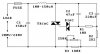
Hi, I have a selfmade (30 years ago) dimmer circuit which uses the schematic attached, except for these values in the schematic:
C1, C2 and C3: 100nF
R1: 12k
R2: 470R
R3: 100k pot
I recently opened the box it had been sitting in for decades and for safety resaons I had to remove a 100nF cap which had been soldered rather unsafely in parallel to C3. Result is now that the dimmer does not go to 0V anymore, at the minimum it lights any load still to about 20%.
For practical reasons (board layout, tight space etc..) I would rather replace a resistor instead of having to solder back a cap parallel to C3 or rather then to replace C3 altogether.
Is a solution with a resistor replacement possibel?
Thanks,
Erik
Edit: the reason my values are different from the schematic simply is that my actual circuit was assembled 30 years ago, and this schematic is just plucked from internet, although it is the same layout for my circuit).
Edit 2: or would the use of polypropylene 400V capacitors be safe and right?
Attachments
Last edited:


 , I ordered some different values from Aliexpress; it will certainly not be a dimension issue in my cramped student-era box.