Continue to Site

Welcome to our site!

Electro Tech is an online community (with over 170,000 members) who enjoy talking about and building electronic circuits, projects and gadgets. To participate you need to register. Registration is free. Click here to register now.

  • Welcome to our site! Electro Tech is an online community (with over 170,000 members) who enjoy talking about and building electronic circuits, projects and gadgets. To participate you need to register. Registration is free. Click here to register now.

Simple Transistor Voltage Regulator Simulation

Status
Not open for further replies.

ACharnley

Member
Hi,

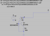
I have a requirement to drop a voltage from 5-36V down to 3.3V with precise (0.5%) accuracy. To do this I've used an accurate LDO (RT9050, 5.5V max) and a simple transistor regulator before it. The current draw is minimal, about 20mA max. The circuit was deemed "complete" and is about to be prototyped by a fab house. The one part I didn't check, because it simulated correctly in LTSpice, was the simple transistor regulator part.

In LTSpice the following screenshot works. I've swapped the transistor out to see how gain affects it but the voltage is stable.

Out of paranoia I built it on a breadboard and found a ~10V increase leads to a 1.5-2V increase on the output. Accuracy increases as the 10K base resistor decreases up to the point enough current is flowing through the zener to make the transistor rather pointless.

Given I have a 36V max input, that's about 6V variance on the output which will blow the precision LDO.

Can anyone explain what's going on, why LTSpice hasn't caught it (LTSpice shows only 0.05V delta between 10 and 30V input)?

Cheers,

Andrew
 

Attachments

  • 1.png
    1.png
    36.8 KB · Views: 274
A 3.9v zener does not have a sharply defined voltage.

Look at Figure 14 on this datasheet: https://www.vishay.com/docs/85764/bzx384.pdf
Zener characteristics.png


With the currents you are putting through the zener via the 10k resistor, you will be operating on the knee of the curve.

JimB
 
Ah!

My bench supply is only 20V so I couldn't tell if the voltage increase was occurring past this point, it looks like it wont. I'm also using a 5.6V Zener (mistake in screenshot) which with the transistor offers about 4.9V to the LDO. As long as it doesn't have a 0.6V variance (by increasing the resistor to say 3.9k) I should be OK?

((36-5.6)/3900 )*(36-5.6) = 0.23W dissipation (inside 500mW limits as I'm using BZT52).
 
Last edited:
hi AC,
Please post your complete LTS asc circuit file.
E
 
LtSpice showed only what you asked of it, but you didn't do the required steps to see if the regulator covers the range of inputs and expected outputs..., or if you are stressing any of the components...

First, here is how to use LtSpice to test the Output Voltage Regulation as a function of Input voltage, V1. The regulator has a 5mA load. The input voltage ranges from 1V to 36V (see X axis). You can see what the minimum input voltage for regulation, about 6V...
vri.png
I plot both the Zener voltage V(z) and the output voltage V(out). Note that the regulator's V(out) changes 163mV as V1 changes from 6V to 36V, or 0.5%. I also plot the power dissipation in the Zener (<20mW, ok) and in Q1 (160mW which is getting up there).

Second, here is how to use LtSpice to test the Output Voltage Regulation as a function of Load current. The input voltage is 36V; you might want to repeat this test at V1=minimum.
vro.png
I vary the output load from 1uA to 10mA. The log of load current is the X-axis.

I plot both the Zener voltage V(z) and the output voltage V(out). Note that the regulator's V(out) changes -240mV as Load current changes from 1uA to 10mA. I also plot the power dissipation in the Zener (<20mW, ok) and in Q1 (310mW which is quite high for that transistor).
 
Last edited:
Usually a simulation uses only "typical" spec devices but in the real world some have minimum specs and others have maximum specs even if they have the same part number.

The datasheet shows you the wide range of "dynamic resistance" of the zener diode which affects its ability of voltage regulation. Heat also affects the output voltage that maybe a simulation ignores.
 
Better to use a simple LM317 regulator circuit adjusted to 5V out as a preregulator (or a LM317HV for more high voltage margin).

Edit: Forgot that this won't work down to a 5V input. :oops:
 
Last edited:
Thanks MikeMI, your LTSpice knowledge is informative (I'm learning it still).

As others have said the issue is the low voltage zener differing it's resistance at low mA's resulting in fluctuation at Vout. I had no idea it occurred until pointed out in the datasheet. It's nearly caught me out elsewhere as I have a 100k resistor + 2.7v zener going to a 3.3v (max) MCU. That would have applied higher than 3.3v, though perhaps the 100k would have protected the mcu's fet from blowing (unsure, don't fancy testing it).

The reason I didn't go for an LM117 is the 2.5v drop. The chip is actually just being used as a bootstrap while a super cap charges to 1V at which point a 5V boost kicks in. I can't guarantee more than 6V input. 6-2.5 = 3.5V. The LDO has a 200mA drop so technically the MCU is under-voltaged, but worse the 6V may be pulsing at low frequency so I need headroom to charge some caps and keep the MCU from resetting.

For the trivial amount of current I need (bootstrap = 3.3v, 20mA max) I opted for the transistor. I would have deleted the transistor and took it straight from the resistor/zener divide if it weren't for the 36V input possibility which would then pose a problem for the zener wattage limit.
 
Last edited:
Status
Not open for further replies.

Latest threads

New Articles From Microcontroller Tips

Back
Top