Continue to Site

Welcome to our site!

Electro Tech is an online community (with over 170,000 members) who enjoy talking about and building electronic circuits, projects and gadgets. To participate you need to register. Registration is free. Click here to register now.

  • Welcome to our site! Electro Tech is an online community (with over 170,000 members) who enjoy talking about and building electronic circuits, projects and gadgets. To participate you need to register. Registration is free. Click here to register now.

Simple Transistor Information!

Status
Not open for further replies.

gibby106141

New Member
Whilst building my cow feeder circuit I came across some issues with the transistor, and understanding detailed operation.

Transistor understanding really does appear to be a black art - but I was thinking is there any way this operation could be dumbed down for people like myself who will only ever build simple circuits?

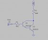
In my application I am using a 2N2222 transistor as a switch -

When I did my electronics theory all them years ago in the training school - I'm sure we were told a base voltage of 0.7v would allow the transistor to operate and allow a larger current to be drawn across the collector and emitter.

However when I was researching these componenets I couldnt find any particular reference to this value.

For the 2N2222 transistor I have a few specific questions:

Is it base voltage or current which operates the transistor?

Does anyone understand why 0.7 v has stuck in my brain?

How do I know what base current/voltage saturates my transistor?

If I have a collector current of 400mA flowing into the transistor how do I calculate the power - so I make sure I dont overheat the unit is it VxI

Is HFE current gain? i.e. the collector current allowed is directly proportional to the base current?

Like I say this has all popped into my head whilst doing the cow feeder circuit - the help for which I really appreciate.

Regards

Mark
 
In a silicon bipolar transistor, such as the 2N2222 the base-emitter junction appears as a diode, and since the forward biased voltage of a silicon diode is about 0.7V, then the normal turn-on voltage of the transistor is also that value.

In practice, it's the base current that turns on the transistor.

The HFE is indeed the current gain, but the data sheet value for that is used for small signal, linear use, not for switching. To fully saturate a BJT as a switch you should use an HFE value of 10 or so (base current 1/10 of the maximum collector current).

To determine the power, you look at the saturation voltage in the data sheet for the collector current (400mA) and multiply those two values together to get the power dissipated when the transistor is on.
 
Thanks for the response so does that mean to fully saturate a 2n2222 i need a base current of 80mA ?

Is a cmos 4093 capable of providing that level of current as an output?

Regards

Mark
 
according t the data sheet for the 4093, no. the source and sink output currents are much lower than that. it would be better to use a TTL schmitt trigger (7414) or second 2n2222 in a darlington configuration to provide the required current gain for saturation.

i have seen 2N2222 transistors driven from TTL outputs in a lot of applications that saturated just fine without "help". the 4093 would most likely need the darlington circuit to saturate. if you have a few 2N2222 transistors, it doesn't hurt to experiment with it. the HFE of a darlington is (Hfe(Q1)*Hfe(Q2))
 

Attachments

  • driver.jpg
    driver.jpg
    11.6 KB · Views: 184
So I guess that does mean to be fully saturated it requires a base current of 80mA

hi Mark,
Thats not correct.

Saturation occurs when all the supply voltage is dropped across the collector load.

example: if the supply was 12V and the relay coil resistance is say 500R then when the current thru the coil is 12/500 = 24mA, the transistor voltage Vce will be around 0.2V

OK.
EDIT: so if in saturation the transistor gain is only 10,,, the Ibase = 24mA/10 = 2.4mA

EDIT2: for your Cowfeed4, the base resistor is 2k2 for say an ideal drive of 12V, [12-0.7]/2200 = 5mA , so thats able to drive a 50mA relay coil.
 
Last edited:
Eric

Once again youve helped me thats the best explanation ive seen on the subject, like i say it was the cow feed circuit which is currently in my kitchen that made me ask the question

Regards

Mark
 
Eric

Once again youve helped me thats the best explanation ive seen on the subject, like i say it was the cow feed circuit which is currently in my kitchen that made me ask the question

Regards

Mark

hi Mark,

I have looked at the Finder 40S 12Vdc relay and they are either 200R or 300R coil versions....
If the current demand for the relay had been much higher I would have used a 2N7000 MOSFET in place of the 2N2222.

In practice the 2N2222 gain is higher than 10 when in saturation at such low Ic currents, I have found them to have a gain of about 15..
 
Eric,
Just to test my understanding –

If I have a simple circuit – a 2N2222 switching the current for a RED LED (SAY)

A red LED requires a voltage of at least 1.6V, and I want to minimise the current through the LED to 15 mA then –

12-1.6 = 10.4 V

10.4V / 0.015 A = 693 ohms ( this is the resistor leading into the collector)

So for the transistor base current to saturate for the load it needs to be at least a tenth of the load current?

One tenth of the load current is 0.015/10 = 0.0015A

The transistor needs a voltage of at least 0.7 volt to overcome the bias of the transistor.

This means my base needs 0.7v & 0.0015A to enable saturation for the desired load.

The supply is again 12v, so the resistor between the 12V supply and the base will be

12V – 0.7V = 11.3V

11.3V/0.0015A = 7553 ohms.

Would this work??

Sorry for being a pain!!! You’ve helped me more than enough already.
Regards
Mark

you don't need to be that exact. the 1.5mA base current is a minimum to saturate at a collector current of 15mA. there would be no problem providing the base current through a 4.7k resistor. as long as you don't exceed the maximum base current for the transistor (probably about 50-60mA for a 2n2222)
 
When I did my electronics theory all them years ago in the training school - I'm sure we were told a base voltage of 0.7v would allow the transistor to operate and allow a larger current to be drawn across the collector and emitter.

However when I was researching these componenets I couldnt find any particular reference to this value.

Check under "Base-Emitter Saturation Voltage". They often give you a min and a max value which are under and over the 0.7V rule of thumb.
 
Eric,
Just to test my understanding –

If I have a simple circuit – a 2N2222 switching the current for a RED LED (SAY)

A red LED requires a voltage of at least 1.6V, and I want to minimise the current through the LED to 15 mA then –

12-1.6 = 10.4 V
Ideally you should also subtract the Vce sat voltage , say 0.2V for you example.
12-[1.6+0.2]

10.4V / 0.015 A = 693 ohms ( this is the resistor leading into the collector)
A 680R would be the nearest preferred value.

So for the transistor base current to saturate for the load it needs to be at least a tenth of the load current?
Its usually assumed that the transistor gain is 10 when the transistor is in Vce saturation.

One tenth of the load current is 0.015/10 = 0.0015A

The transistor needs a voltage of at least 0.7 volt to overcome the bias of the transistor.

This means my base needs 0.7v & 0.0015A to enable saturation for the desired load.
You would not normally tackle the problem this way.

The supply is again 12v, so the resistor between the 12V supply and the base will be
12V – 0.7V = 11.3V
This is the method in common use.

11.3V/0.0015A = 7553 ohms.
Would this work??
Yes, I would use a 6800R , preferred value

Regards
Mark

Hi Mark,
The detail to watch out for is the variation in LED forward drop voltages, even for the same type RED's you can get a +/-0.2V spread.

This wouldn't make much difference in your example, but when connecting LED's in series, this Vdp spread can lead to over currents in the LED chain.
Ideally if connecting in a series chain I would measure the individual LED drops to get the total drop.

This image may help.
 

Attachments

  • LEDcolours.gif
    LEDcolours.gif
    12.2 KB · Views: 179
remember that the Max Vf of the B-E junction is just that. as the data sheet says it's an ABSOLUTE MAXIMUM, which means don't go there if you want the transistor to survive. also understand that if you are driving a relay (you used an LED as an example, but other posters mentioned relays) you need a snubber diode across the relay to keep reverse voltage spikes from damaging the transistor. the reverse voltage spikes appear when the transistor is turned off, and the magnetic field in the relay collapses.
 
Last edited:
Thanks all for the replies - I do struggle with transistor terminology and think in general terms its far too complicated for novices like myself - thats why I like the rule of thumb methods, i.e. not fit for all circuits but probably suitable for anything someone like myself would try and do.

Just one more question is Vce saturation voltage essentially the voltage drop across the transistor collector and emitter - and I guess for more complex or whats the word?? tolerance critical circuits that it needs taking account of?

Mark
 
mark your post are actualy helpful to others like myself, you ask intelligent questions in a concise manner and have obviously tried to research and understand the subject yourself. personaly i see no reason to appologise and i myself are learning as much as you are from the replies.
one question tho as i myself am a farmer....if your feeder is in the kitchen are you realy feeding the cows there :O
 
Ghostman,,

I live on a working farm, and work there when I can, but actually work as a E&I technician, the trouble is we don't actually deal with electronics we work more at the full system level & electrical systems, electronics was something I did do years ago at college, but never really got into it. As I get older I realise its something I really want to learn more about - and be able to understand the basics to at least get some fun out of it - I don't ever believe I will be an expert, but to have a working knowledge would be great, and to obviously apply it to the farm is an added bonus.

The prototype cow feeder is sat in the kitchen - I can't help but tinker with it evertime I walk past it, to much ribbing by my partner!!

My next project is hopefully a cubicle scraper controller - we have automatic scrapers, but the existing control units are extortionate, thinking on the terms of some sort of flip flop to control them, with a single magnetic limit switch input for changing direction and stopping.

Its suprsing how many people on here are closet farmers!!!

Regards

Mark
 
Just one more question is Vce saturation voltage essentially the voltage drop across the transistor collector and emitter - and I guess for more complex or whats the word?? tolerance critical circuits that it needs taking account of?

Yes, you got it. That one can bite you sometimes - the "rule of thumb" here is .1V for a saturated bipolar, but you can see from the curves it's considerably higher when there's higher currents involved, well over a volt. So you figure the transistor is only going to dissipate a 1W at 10A, and it's actually trying to burn off 10W...
 
i got started in electronics with a huge incubator project as we breed rare birds and fowl (amongst other things) we are not a huge farm at around 240 acres now. but keeps us busy :D electronics are very handy around the far ;)
 
Status
Not open for further replies.

Latest threads

Back
Top