Hello all,
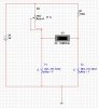
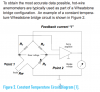
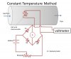
I may sound stupid but does anyone have a simple schematic or know how to build a thermal air flow sensor/meter using two pt100, resistors, variable resistor, multimeter & of course a voltage source? I want to see and build the working principle behind the thermal flow meter. I don't really get how it works. If anyone can help explain in simple terms that'll be great. I do know that you have to use a wheatstone bridge. One sensor is for reference temperature and the other one is heated to maintain the temp difference when the air flows. I'm not even sure if the circuit I did below is in the correct direction. Someone told me instead of using self heating circuit I can rub it with my fingers. I've no electronic background thus my knowledge is limited, making me turn for help here.
I may sound stupid but does anyone have a simple schematic or know how to build a thermal air flow sensor/meter using two pt100, resistors, variable resistor, multimeter & of course a voltage source? I want to see and build the working principle behind the thermal flow meter. I don't really get how it works. If anyone can help explain in simple terms that'll be great. I do know that you have to use a wheatstone bridge. One sensor is for reference temperature and the other one is heated to maintain the temp difference when the air flows. I'm not even sure if the circuit I did below is in the correct direction. Someone told me instead of using self heating circuit I can rub it with my fingers. I've no electronic background thus my knowledge is limited, making me turn for help here.
Attachments
Last edited:
")
