Continue to Site

Welcome to our site!

Electro Tech is an online community (with over 170,000 members) who enjoy talking about and building electronic circuits, projects and gadgets. To participate you need to register. Registration is free. Click here to register now.

  • Welcome to our site! Electro Tech is an online community (with over 170,000 members) who enjoy talking about and building electronic circuits, projects and gadgets. To participate you need to register. Registration is free. Click here to register now.

Simple stepper driver

Status
Not open for further replies.

Centretek

New Member
Hi All,
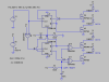
I have been attempting to design a stepper motor driver, to drive a telescope in sidereal time. It could also be used for a solar tracker.
Anyway the cct I have come up with is attached. Please give it a look and let me know what glaring errors I may have made.
BTW R2=4K7
 

Attachments

  • Stepper drive.gif
    Stepper drive.gif
    226.7 KB · Views: 1,134
Last edited:
Firstly, use a crystal oscillator instead of a 555. The frequency accuracy of the 555 means you will end up always fidding with it.

I made a frequency converter for a 36" telescope, to stabilise the 50Hz mains, because the mains frequency variation was too much for that telescope, and mains in the UK is far more accurate than a 555.

The rest of this assumes that L1 and L2 are on the same pole, just opposite ways round, like the diagram implies.

You have the phase sequence wrong. You should drive L1, L3, L2, L4

You shouldn't just drive one phase at a time on the stepper motor. It might be OK, but it might not, as you are turning on one phase at the same time as you are turning off another, with nothing to keep the motor held at the time.

It is usual to drive 2 phases at a time, like this:-

L1 and L3
L2 and L3
L2 and L4
L1 and L4

For smoother operation, you want:-

L1 and L3
only L3
L2 and L3
only L2
L2 and L4
only L4
L1 and L4
only L1

It looks like a job for a microcontroller.
 
I knew it was too easy. OK back to the drawing board.
Thanks for the help.

BTW Are you willing to share the schematic for your crystal control ?
 
Last edited:
Simple stepper drive

OK revision #1

I have used 8 o/p s from the 4017 to enable the smoother drive.

L1 and L3 o/p 0
only L3 1
L2 and L3 2
only L2 3
L2 and L4 4
only L4 5
L1 and L4 6
only L1 7
8 wired to reset.

Paths in schematic are colour coded to help follow lines.

I probably need resistors on each o/p to keep 'low' at less than the switching voltage of the 2N2222 s
 

Attachments

  • 555_4017.gif
    555_4017.gif
    101.9 KB · Views: 829
The schematic wouldn't be much help to you as I was driving a synchronous motor.

Your design wasn't that far off the mark.

You had a frequency generator, the 555. Unfortunately it wouldn't have been accurate enough.

There is a device to create a sequence to drive the stepper motor, the CD4017. It just needs adapting to the correct sequence.

There are the drivers for the motor phases. They look fine.

You could add some OR gates, or use diodes to give you the same effect, and still use the CD4017. If you "OR" the 0 and the 1 for to drive L1, the 1 and the 2 to drive L3, etc, that would work.

For the better scheme, move the reset to the 8 line, then wire it so that 0, 1 or 2 will drive L1,
2, 3 or 4 will drive L3
4, 5 or 6 will drive L2
6, 7 or 0 will drive L4

If you pick the crystal frequency correctly, you could use a CD4060 or two to divide the crystal frequency to give you the speed you want.

It is difficult to have a finely adjustable and very accurate frequency. You either need a good phase lock loop or direct digital synthesis.
 
Hi Stargazer,

There are a lot of devices which are capable of driving a
stepper motor but using a 4017 for that purpose is a bit silly.
Keep the 555 part and replace the rest with this circuit.
If you don't need/want a direction control you can build it
without U10 & U11, it will work equally well.
If you can tell me how many steps your motor has I'll see
what I can do for the crystal oscillator.

on1aag.
 

Attachments

  • Stepper 2 schematic.PNG
    Stepper 2 schematic.PNG
    16.9 KB · Views: 576
  • Stepper Plots.PNG
    Stepper Plots.PNG
    14.2 KB · Views: 343
Last edited:
I really don't think that there is anything wrong with the 4017 circuit.

You could use four 3-input OR gates instead of the diodes but there is nothing wrong with the diodes.

There are two major problems with the flip-flop circuit as it is. Firstly, the direction is random, and it depends on the start condition of the two flip-flops.

Secondly, the 4070 XOR gates won't reverse the direction. You should only have the XOR gates on the outputs from one of the flip-flops, not both.

I have attatched a diagram of one way of getting quadrature outputs from two flip-flops.
 

Attachments

  • quadrature.gif
    quadrature.gif
    5 KB · Views: 339
Diver300 said:
There are two major problems with the flip-flop circuit as it is. Firstly, the direction is random, and it depends on the start condition of the two flip-flops.

Yes, but you made a slight error. This attached diagram will work.

Diver300 said:
Secondly, the 4070 XOR gates won't reverse the direction. You should only have the XOR gates on the outputs from one of the flip-flops, not both.
I disagree. You must invert both Q and not-Q in order to change the phase by 180 degrees (change +90 to -90)
 

Attachments

  • quadrature.gif
    quadrature.gif
    5.9 KB · Views: 235
Bob Scott said:
Yes, but you made a slight error. This attached diagram will work.

Yes, sorry. One D is fed from Q of the other flip flop, the other D is fed from not-Q of the first flip flop.

Bob Scott said:
Diver300 said:
Secondly, the 4070 XOR gates won't reverse the direction. You should only have the XOR gates on the outputs from one of the flip-flops, not both.
I disagree. You must invert both Q and not-Q in order to change the phase by 180 degrees (change +90 to -90)

That is what I meant. You need to invert both Q and not-Q to reverse it. However, you should only invert either the sine pair or the cosine pair, not all four signals.
 
Status
Not open for further replies.

Latest threads

New Articles From Microcontroller Tips

Back
Top