Continue to Site

Welcome to our site!

Electro Tech is an online community (with over 170,000 members) who enjoy talking about and building electronic circuits, projects and gadgets. To participate you need to register. Registration is free. Click here to register now.

  • Welcome to our site! Electro Tech is an online community (with over 170,000 members) who enjoy talking about and building electronic circuits, projects and gadgets. To participate you need to register. Registration is free. Click here to register now.

Simple Solar Tracking circuit

Status
Not open for further replies.

helpmonkey

New Member
I posted this in projects but got no responce? ... I designed this circuit and would like some input on it from anyone who is experienced with op-amps. The circuit works but I would like to make it more effecient. The component values can be found here **broken link removed** ... the circuit is powered by two 12volt batteries in series providing +/- 12 volts.

**broken link removed**
 
Last edited:
This circuit will empty the batteries because all the time there is just a little difference between east and west led, the motor will be feeded with a little voltage that will do nothing but heat the transistors, until the motor start to run (in random time).

A lot better way to do this is to introduce a schmitt-trigger (or two) so you wont waste too much energy over time. Also you can use a H-bridge so you can use one battery only.
 
No there is not an imbalance all the time? ... the comparator stays balanced unless the tracker is updating or reseting... the issue I am having is during tracking as the first west led begins to be exposed the voltage swings positive to slowly which consumes power and decreases efficiency... I can compensate by increasing the gain but then the comparator becomes to sensitive and does not balance at zero volts... I have tried to incorporate a schmitt trigger but cannot get it to work properly (I am not experienced with schmitt trigger configurations)... Also this circuit is designed as simply as possible so that it can be assembled by anyone even without electronics experience... I would also like to note that all the components are recycled from scrap electronics. Any suggestions would be much appreciated.
 
No there is not an imbalance all the time?
That should be correct. I'm not sure that imbalance is the right term.

Say the motor is positioned exactly at right position so that the differentiate circuit provide exactly zero volt out. Just a couple of minutes later, the sun may have changed position enough to provide some voltage out. But that voltage will rise very slowly. And motor may not start spinning before voltage reach how much? 1,5V?
Before the motor start to run, the motor (but mostly the transistors) have wasted some energy while the motor didn't run, but had a little voltage over it.

You haven't provided any data for motor so I doesn't know how much voltage it need to start running. You could always try to make the difference amplification higher. That will cause the motors voltage to rise more quickly and therefore the circuit will waste less energy each tme the motor runs. However, that will also get the motor to run more frequently, and at a shorter distance (angle) each time.

[EDIT]
I also see another big mistake on the schematic. The diode over the motor will effectly prevent it to run while the PNP transistor conduct. Is the motor supposed to run both ways?
 
Last edited:
Oh man thnks Grossel I never did include that diode in my test circuit but yes that would make sense as it would be forward biased when the PNP was switched on ...I will delete it from the schematic... the motor is just a small 12 volt printer motor it draws about 200mA it will turn at about 2volts.... when testing the circuit with the resistor values as specified the voltage will start at zero ... after about 1min the voltage (measured across the motor) will begin to rise slowly ... it takes about 15 seconds to hit 2volts and the motor turns ... most times the voltage will fall back to zero bit occasionally the voltage drops to .5v ... it will climb back up to 2volts .. update and then back to zero... this repeats again after about a minute...
 
I have been experimenting with schmitt triggers as Grossel suggested... the 4558DX is a dual op-amp which makes it convenient ... I am trying to make a non-inverting trigger but without much success... another possibility is to use a 555 and wire it as a on/off timer to switch the common from the power supply although this would probably require a relay which I would like to avoid.
 
I did some reading about using LEDs as photo-detectors, and got motivated to try an experiment. I tried some moderately bright red LEDs that I have laying around, similar to these. They are in a water-clear T1 3/4 lens. I do not know their viewing angle; i'm guessing they are the 30 degree variety, because they were bought for indicators.

Shunting an unbiased LED with a 1megΩ resistor, under outdoor illumination on a sunny day, I get about +1.5V anode to cathode, using a Fluke 73 DMM (>10meg input impedance). The LED is directive, consistent with the "viewing angle" shown on the referenced data sheet.

I then connected two LEDs in parallel, which approximately doubled the output voltage, indicating that the current produced by the LED (into the 1megΩ resistor) also doubled. I then reversed one of the LEDs so that the pair is connected in inverse parallel with the 1megΩ resistor, and bent their leads so that their optical axes diverged by about 45 degrees.

The inverse-parallel 2 LED array produces +- 1400mV as the array is panned across the sun, with zero volts out when the optical axes of the two LEDs roughly bisects the angle formed by the two diverging LEDs. Seems like this could be used to drive a Sun Seeker, because the 2 LED array puts out a signal which goes from +1400mV to zero to -1400mV as the sun angle changes.

To construct a Sun Seeker using the inverse-connected two LED array, you may have to put a small baffle that splits the angle between the two LEDs, orthogonal to the sun's path. In the morning, when the array is parked looking at the wrong horizon, the baffle would cast a shadow onto the west LED, allowing the East LED to dominate to drive the seeker toward the East horizon. After the seeker locks on, the baffle would be edge-on to the sun, so the differential mode of the array would not be effected by the presence of the baffle.

Using this idea, I modified your circuit to include a deadband near the balance point, and made it so that the motor switching transistors use a Darlington connection to minimize power dissipation while the motor is running.

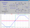
Attached is a schematic and a running LTSpice simulation. The Solar Flux is simulated using a current source, which produces a voltage across the LEDs similar to what I measured outside. I use two comparators to implement the deadband region near the balance point, so the motor is switched off cleanly once the seeker centers itself. The transistors dissipate less than 1/2W when switching 1A. Substituting a PFET and NFET for the transistors lowers the part count, if you have the FETs.
 

Attachments

  • SolarSeeker.png
    SolarSeeker.png
    53.8 KB · Views: 3,687
awesome Mike ... I will breadboard this as soon as I get a chance ... I am wondering if I could add more (maybe just one on each side) leds as when the tracker ends up facing west in the evening both leds will be facing almost totally west and the east led will probably not pick up the sun untill late in the morning... ???
 
I'm guessing that just two LEDs with the baffle between them will work fine. Making an array with two West; two East will work too; just do the inverse parallel thing with two pointing each way.
 
I breadboarded the circuit ... substituted ... LM339A->AN6912 ... TIP42C->B1185 ... TIP3055->D2058 ... and 2n4401/4403->3904/3906 ... looks good testing it with a led illuminating the input leds... it also works fine using my origional LED sensor array with 4 leds in each row (8 in all) the rows are connected in reverse parallel... its cloudy here but I will test it outside as soon as the weather clears... again awesome design Mike

**broken link removed**
 
Last edited:
the sun is shinning... I modified the sun sensor and removed the the two leds closest the the shadow vane (one west and one east... I also increased R9 to 1K-ohm... it seems to be working nicely... it updates about every 60 seconds... I will build a new sensor array and I think we can do away with the shadow vane altogether? ... I plan on using just two leds on each side ... all the transistors are cold which is a good sign...:)

circuit_4_001.jpg
 
Last edited:
I am now using 6 LEDs ...3 west and 3 east... for the sensor with no shadow vane. I tried 2 LEDs on each side but it left dead spotsin the rotation when the tracker would update after a cloudy period or reset in the morning.

sensor_v4.jpg
 
Hi guys! I'm a raw beginer with electronics and this tracker gave me incentive to learn a bit! I'd love to use this circut for a solar engine I'm building.
 
eddie6675 ... I will be posting the schematic and assembly instruction on my website **broken link removed** ... (the schematic is also posted above in MikeMl's post) I should have details posted on the website by this weekend. We are still testing the circuit.... have had some oscillation problems ... have increased the value of R9 to 1.5K which eliminates the oscillations but decreases tracking sensitivity... the current LED sensor has the east/west LEDs seperated by 60deg ...
 
Last edited:
wow..very nice site! I printed the cds cell plans and have all the parts your circut need less the cds cells..Your new development seems easier to grasp for a newbie like me though. The LEDs seem easier to get locally for me too. I'm glad there's people like you around who are willing to be a teacher! If there was a way I can help with mechanical problems I'll be glad to at least contribute that to the effort. :)
 
eddie6675 you can get the cds cells from cheap battery powered solar garden lights ... which also include a clear white LED that should work if you making the LED sensor. I do have some mechanical issues... I plan on building a slew drive for the next version... I am going to use a scrap battery powered drill motor and planetary gears to drive a worm gear made from a threaded rod which will in turn drive a large spur gear... problem where do I find large spur gears ... something around 6 inch diameter should be good... any ideas?
 
Status
Not open for further replies.

Latest threads

New Articles From Microcontroller Tips

Back
Top